Taxonomy of BSPP fittings
v0.145.0.349
Table of Contents
- 1. Introduction
- 2. Faceted Structure
- 3. Facet — Thread Form (BSPP, BSPT, NPT)
- 4. Geometry Facet — Enumeration
- 5. Facet — Gender (F-02)
- 6. Facet — Nominal Size (F-04)
- 7. Facet — Sealing Mechanism (F-05)
- 8. Facet — Material (F-06)
- 9. Facet — Pressure and Temperature Rating (F-07)
- 10. Facet — Application Context (F-08)
- 11. Topological Foundations
- 11.1. Two framings, in parallel
- 11.2. Prior art and related work
- 11.3. The loose view: bending, stretching, counting ends
- 11.4. The fitting set, sorted by port count
- 11.5. Framing I: the fluid path (negative space)
- 11.6. Framing II: the solid body
- 11.7. Where the two framings agree, and where they diverge
- 11.8. The rigorous pass: the fitting cobordism category
- 11.9. The objects: port mouths as circle-unions
- 11.10. The morphisms: fitting bodies as cobordisms
- 11.11. The invariants, and the structure theorem
- 11.12. Where the engineering decorations live
- 11.13. The solid-body framing does not submit as cleanly
- 11.14. Findings
- 11.15. The decision, now made: a single ancestor
- 11.16. Relation to the model library
- 12. Coverage map vs Wikipedia Piping and plumbing fitting
- 13. Facet Audit against ISO 12006-2 and UniClass 2015
- 14. Validation Scenarios
- 14.1. SC-01 — Connect a pump outlet to a 1/2" hose
- 14.2. SC-02 — Reduce from 3/4" to 1/2" in a horizontal line
- 14.3. SC-03 — Add a tap to an existing horizontal line
- 14.4. SC-04 — A connection that "fits" but seeps after a thermal cycle
- 14.5. SC-05 — Replace a leaking compression joint with a threaded one
- 14.6. SC-06 — Specify a fitting for hot potable water
- 14.7. SC-07 — Choose between concentric and eccentric reducer
- 14.8. SC-08 — High-pressure pneumatic line for a workshop
- 14.9. SC-09 — Read a fitting marking
- 15. Glossary
- 16. Bilingual Labels — English ↔ French
- 16.1. Thread forms (~ formes de filetage )
- 16.2. Geometry and ports (~ géométrie et orifices )
- 16.3. Gender (~ genre du filetage )
- 16.4. Sealing (~ étanchéité )
- 16.5. Materials (~ matériaux )
- 16.6. Pressure, temperature, and ratings (~ pression, température, classification )
- 16.7. Approvals and markings (~ agréments et marquages )
- 16.8. Tools, accessories, and trade terms (~ outils, accessoires, vocabulaire de métier )
- 16.9. Application terms (~ termes d'application )
- 16.10. Practical sizing note — French DI×DE designations and the European DN system
- 16.11. What this section does not cover
- 17. Sources and Attributions
List of Figures
- Figure 1 BSPP male straight-thread fitting with a hex flange and a captive O-ring seated against the flange's underside.
- Figure 2 55° Whitworth thread profile, the form shared by BSPP and BSPT.
- Figure 3 Historical comparison plate from William Sellers' 1864 paper proposing the 60° symmetric thread profile.
- Figure 4 Straight (nipple-family) archetype gallery: twelve configurations of the BSPP straight fitting in a 4 × 3 grid, three-quarter view (still viewpoint lat 35°, lon 270°).
- Figure 5 Straight archetype cutaway companion: the same twelve configurations as fig:straight-archetypes, each sectioned on its mid-plane (BOSL2 BACK cutaway) so the camera looks into the bore.
- Figure 6 Pipe archetype gallery: twelve configurations of bsppfit_pipe() in a 4×3 grid — the top row sweeps the four port-gender combinations (M×M, M×F, F×M, F×F) at G1/2, the middle row crosses length with size, and the bottom row holds specials (a long run, a larger size, the smallest size, a thick-wall variant).
- Figure 7 Pipe archetype cutaway companion: the same twelve configurations as 6, each sectioned on its mid-plane (BOSL2 BACK cutaway) so the through-bore is visible.
- Figure 8 Elbow archetype gallery: twelve configurations of the BSPP elbow in a 4 × 3 grid, three-quarter view (still viewpoint lat 30°, lon 315°).
- Figure 9 Elbow archetype cutaway companion: the same twelve configurations as fig:elbow-archetypes, each sectioned on its mid-plane (BOSL2 BACK cutaway) so the camera looks into the bore.
- Figure 10 Reducer archetype gallery: twelve configurations of the BSPP reducer in a 4 × 3 grid, three-quarter view (still viewpoint lat 35°, lon 270°).
- Figure 11 Reducer archetype cutaway companion: the same twelve configurations as fig:reducer-archetypes, each sectioned on its mid-plane (BOSL2 BACK cutaway) so the camera looks into the bore.
- Figure 12 Cap archetype gallery: twelve configurations of the BSPP cap in a 4 × 3 grid, three-quarter view (still viewpoint lat 35°, lon 270°).
- Figure 13 Cap archetype cutaway companion: the same twelve configurations as fig:cap-archetypes, each sectioned on its mid-plane (BOSL2 BACK cutaway) so the camera looks into the head.
- Figure 14 Plug archetype gallery: twelve configurations of the BSPP plug in a 4 × 3 grid, three-quarter view (still viewpoint lat 35°, lon 270°).
- Figure 15 Plug archetype cutaway companion: the same twelve configurations as fig:plug-archetypes, each sectioned on its mid-plane (BOSL2 BACK cutaway).
- Figure 16 Union archetype gallery: twelve configurations of the BSPP union in a 4 × 3 grid, three-quarter view (still viewpoint lat 35°, lon 270°).
- Figure 17 Union archetype cutaway companion: the same twelve configurations as fig:union-archetypes, each sectioned on its mid-plane (BOSL2 BACK cutaway) so the camera looks into the bore.
- Figure 18 Hex-bush archetype gallery: twelve configurations of the BSPP reducing bush in a 4 × 3 grid, three-quarter view (still viewpoint lat 35°, lon 270°).
- Figure 19 Hex-bush archetype cutaway companion: the same twelve configurations as fig:hexbush-archetypes, each sectioned on its mid-plane (BOSL2 BACK cutaway) so the camera looks into the bore.
- Figure 20 Hose-tail archetype gallery: twelve configurations of the BSPP hose tail in a 4 × 3 grid, three-quarter view (still viewpoint lat 35°, lon 270°).
- Figure 21 Hose-tail archetype cutaway companion: the same twelve configurations as fig:hosetail-archetypes, each sectioned on its mid-plane (BOSL2 BACK cutaway) so the camera looks into the bore.
- Figure 22 Manifold archetype gallery: twelve configurations of the unified branch-fitting class in a 4 × 3 grid, three-quarter view (still viewpoint lat 35°, lon 270°).
- Figure 23 Manifold archetype cutaway companion: the same twelve configurations as fig:manifold-archetypes, each sectioned on its mid-plane (BOSL2 BACK cutaway) so the camera looks into the bore.
- Figure 24 Gender at the geometry level: a male fitting (left) and a female fitting (right) of the G-01 straight family, same size (G1/2) and hex body, so gender is the only difference.
- Figure 25 Gender comparison, cutaway companion: the same male (left) and female (right) fittings sectioned on the mid-plane (BOSL2 BACK cutaway).
- Figure 26 Cross-section of a bonded seal washer compressed under a hex-headed bolt.
- Figure 27 Cap, default variant (single fitting; viewpoint lat 35°, lon 270°).
- Figure 28 Cap, default variant, cutaway (BOSL2 BACK) showing the bore.
- Figure 29 Cross, default variant (single fitting; viewpoint lat 35°, lon 270°).
- Figure 30 Cross, default variant, cutaway (BOSL2 BACK) showing the bore.
- Figure 31 Elbow, default variant (single fitting; viewpoint lat 35°, lon 270°).
- Figure 32 Elbow, default variant, cutaway (BOSL2 BACK) showing the bore.
- Figure 33 Hex bush, default variant (single fitting; viewpoint lat 35°, lon 270°).
- Figure 34 Hex bush, default variant, cutaway (BOSL2 BACK) showing the bore.
- Figure 35 Hose tail, default variant (single fitting; viewpoint lat 35°, lon 270°).
- Figure 36 Hose tail, default variant, cutaway (BOSL2 BACK) showing the bore.
- Figure 37 Manifold, default variant (single fitting; viewpoint lat 35°, lon 270°).
- Figure 38 Manifold, default variant, cutaway (BOSL2 BACK) showing the bore.
- Figure 39 Nipple, default variant (single fitting; viewpoint lat 35°, lon 270°).
- Figure 40 Nipple, default variant, cutaway (BOSL2 BACK) showing the bore.
- Figure 41 Plug, default variant (single fitting; viewpoint lat 35°, lon 270°).
- Figure 42 Plug, default variant, cutaway (BOSL2 BACK) showing the bore.
- Figure 43 Reducer, default variant (single fitting; viewpoint lat 35°, lon 270°).
- Figure 44 Reducer, default variant, cutaway (BOSL2 BACK) showing the bore.
- Figure 45 Tee, default variant (single fitting; viewpoint lat 35°, lon 270°).
- Figure 46 Tee, default variant, cutaway (BOSL2 BACK) showing the bore.
- Figure 47 Union, default variant (single fitting; viewpoint lat 35°, lon 270°).
- Figure 48 Union, default variant, cutaway (BOSL2 BACK) showing the bore.
- Figure 49 Three hose-clamping mechanisms photographed side by side.
1. Introduction
This document captures the taxonomy of British Standard Pipe Parallel (BSPP) fittings, with BSPT and NPT present as adjacent classes for confusion-avoidance (per Concept.org and the scoping decision recorded in ResearchJournal.org).
2. Faceted Structure
The taxonomy is faceted rather than strictly hierarchical: a fitting is described by an independently varying set of attributes, and any tree-like presentation is a view over the facets, not the structure itself.
2.1. Facet inventory
The facets identified for BSPP fittings are:
- F-01
- Geometry — straight, elbow (45°, 90°), tee (equal, reducing), cross, reducer (concentric, eccentric), cap, plug, union, nipple, hex bush, hose tail, etc. See Geometry Facet — Enumeration.
- F-02
- Gender — male, female, mixed (e.g., male × female elbow). Captures which end mates with what. See Facet — Gender.
- F-03
- Thread form — BSPP (the centre), BSPT, NPT (adjacent). The taxonomy does not enumerate every thread form globally; only those needed for confusion-avoidance. See Facet — Thread Form.
- F-04
- Nominal size — 1/8", 1/4", 3/8", 1/2", 3/4", 1", etc. Note the BSPP convention: nominal size refers to bore, not thread OD. See Facet — Nominal Size.
- F-05
- Sealing mechanism — bonded seal washer, O-ring, PTFE tape, anaerobic pipe sealant. The choice depends on thread form: BSPP (parallel) seals on a face or O-ring; BSPT and NPT (tapered) seal on the threads themselves. See Facet — Sealing Mechanism.
- F-06
- Material — brass (most common), stainless steel, plain steel, plastics (PP, PVC, nylon for low-pressure). See Facet — Material.
- F-07
- Pressure / temperature rating class — general purpose, high pressure, food grade, gas. Often expressed as a manufacturer's class or as a working-pressure number in bar. See Facet — Pressure and Temperature Rating.
- F-08
- Application context — plumbing (water), pneumatic (compressed air), hydraulic (oil, glycol), gas. Some facets (sealing mechanism, material, pressure rating) are constrained by application. See Facet — Application Context.
The promotion of one or two facets as primary navigation for end-user-facing selection guidance is a downstream design decision, recorded with rationale in ResearchJournal.org when it is taken.
2.2. Independence and constraints
The facets are nominally independent: any value combination is describable. In practice some combinations are excluded by physics or by trade convention:
- Plastic + high pressure is excluded by burst strength.
- BSPP + thread sealant only does not seal: BSPP requires a face seal (washer or O-ring), regardless of how much PTFE tape is added.
- Food-grade + plain steel is excluded by hygiene rules (food-grade requires stainless or food-grade brass).
These constraints are noted in the corresponding facet sections, not in a separate constraint table. The validation scenarios in Validation Scenarios exercise the confusion-avoidance constraints, which are the most instructive.
3. Facet — Thread Form (BSPP, BSPT, NPT)
3.1. BSPP — British Standard Pipe Parallel
Standardised in ISO 228-1 and BS EN ISO 228. The thread is parallel (cylindrical), with a 55° symmetric Whitworth profile. Sealing is achieved by a face seal (bonded seal washer, O-ring) or by PTFE tape on combined sealing surfaces — not by the threads themselves.
Designation prefixes: G (e.g., G1/2 for 1/2-inch BSPP).
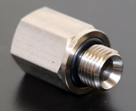
Figure 1: BSPP male straight-thread fitting with a hex flange and a captive O-ring seated against the flange's underside. The thread is parallel along its length (constant outside diameter); the seal is made on assembly when the O-ring is compressed between the male flange and the female face — the threads themselves are not the sealing surface. Photograph by Kees08, CC BY-SA 4.0, via Wikimedia Commons. See also Sources and Attributions.
3.2. BSPT — British Standard Pipe Taper
Standardised in ISO 7-1 and BS EN 10226-1. The thread is tapered (see The 1:16 taper, in plain numbers below for what that means), with a 55° Whitworth profile (same as BSPP). Sealing is achieved on the threads themselves with PTFE tape, pipe sealant, or anaerobic compound.
BSPT defines three designation prefixes, one male and two female. The pair to use depends on what is on the other side:
R- male, tapered. External thread tapered 1:16. The
workhorse male BSPT thread. Example:
R 1/2. Rc- female, tapered. Internal thread tapered 1:16,
mirroring the
Rmale. This is the standard partner forRwhen both sides are dedicated tapered threads. The wedging action between the two tapers does most of the sealing work; the sealant fills the residual helical gap. Example:Rc 1/2. Rp- female, parallel. Internal thread is cylindrical
(not tapered), with the same 55° Whitworth profile and the
same nominal size as the corresponding
Rmale.Rpexists because cylindrical female threads are easier and cheaper to machine than tapered ones, especially in mass-produced bodies. The seal in anR×Rpjoint relies more on thread sealant or PTFE tape filling the gap than on a wedging fit. Mechanically less robust under cycling thanR×Rc, but very common in practice. Example:Rp 1/2.
So when shopping for "1/2-inch BSPT female", the user must
distinguish Rc 1/2 from Rp 1/2: both are female, both are
1/2 inch, both are BSPT, but the internal thread is taper in
one and parallel in the other.
3.2.1. The 1:16 taper, in plain numbers
The notation 1:16 describes a taper rate: the thread diameter decreases by 1 unit for every 16 units of axial length. So:
- Over 16 mm of thread length, the diameter shrinks by 1 mm (radius shrinks by 0.5 mm per side).
- Over 32 mm, the diameter shrinks by 2 mm.
The same 1:16 rate is used by NPT. The geometric effect is that, as a tapered male is screwed into a matching tapered female, the threads bind progressively tighter — this is the wedging action that produces the thread-borne seal.
The angle equivalent is approximately 3.58° between the
cone surface and the thread axis (1.79° half-angle), but the
"1:16" form is the one used in the standards and in shop
practice.
3.3. NPT — National Pipe Thread (American)
3.4. Comparison
| Aspect | BSPP | BSPT | NPT |
|---|---|---|---|
| Standard | ISO 228 | ISO 7 | ANSI/ASME B1.20.1 |
| Thread profile | 55° Whitworth | 55° Whitworth | 60° American |
| Parallel or tapered | Parallel | Tapered (1:16) | Tapered (1:16) |
| Seals on | Face / O-ring | Threads | Threads |
| Designation prefix | G | R / Rp / Rc | NPT |
| Designation example | G1/2 | R1/2 | 1/2 NPT |
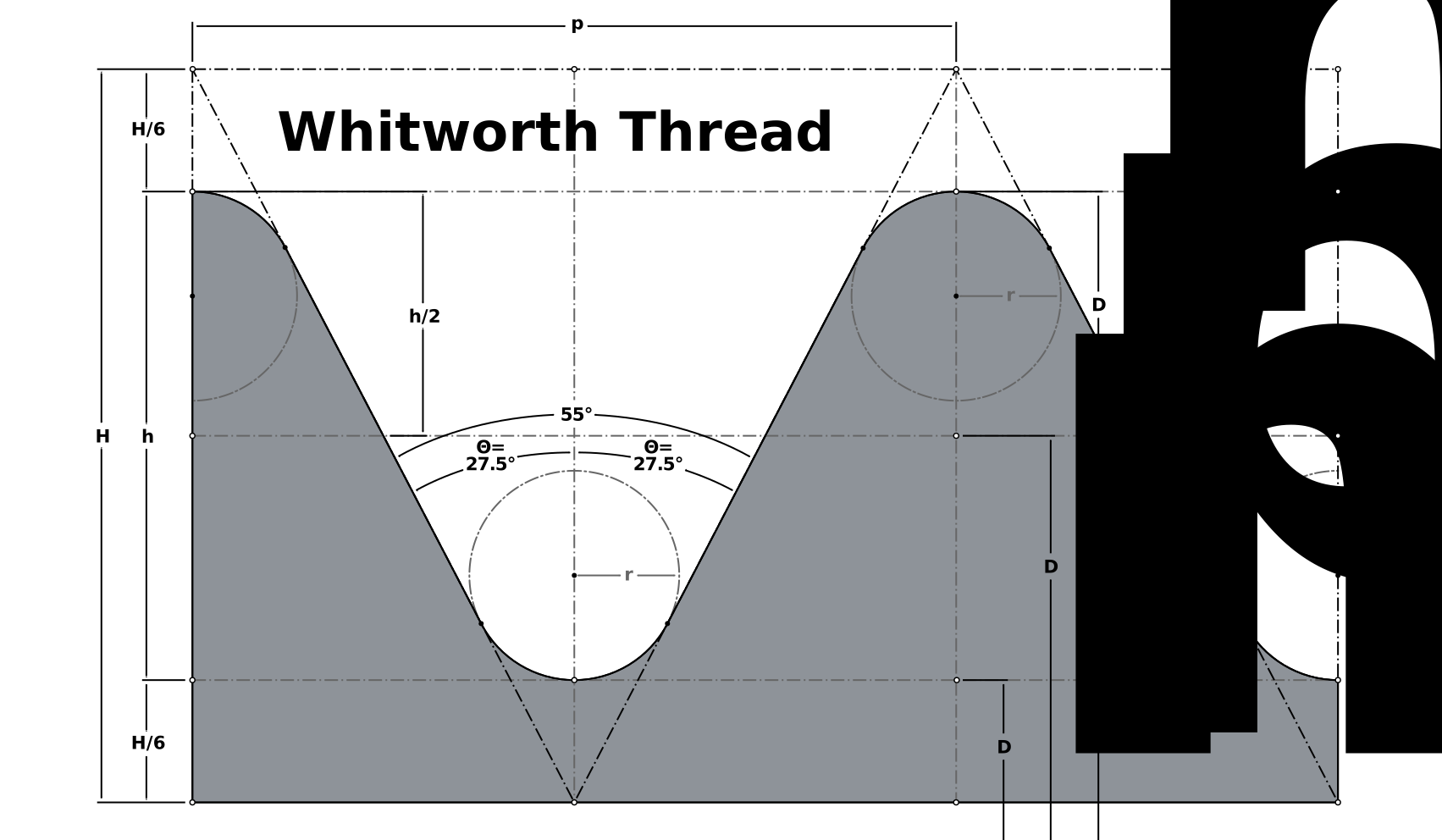
Figure 2: 55° Whitworth thread profile, the form shared by BSPP and BSPT. Symmetric flanks meeting at a 55° included angle; crests and roots are rounded (not flat as in the 60° American profile used by NPT). Diagram by Tjt263; vectorised by AntiCompositeNumber. CC BY-SA 4.0, via Wikimedia Commons. See also Sources and Attributions.
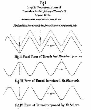
Figure 3: Historical comparison plate from William Sellers' 1864 paper proposing the 60° symmetric thread profile. Informational, not normative. The plate shows three thread forms: the "usual form… best workshop practice" of the period (top), the Whitworth 55° profile with rounded crests (middle, "Form of Thread introduced [by] Mr Whitworth"), and Sellers' own proposed 60° profile with truncated crests (bottom, "Form of Thread proposed by Mr Sellers"). The Whitworth profile (middle) is the form used by BSPP and BSPT; the Sellers profile (bottom) is the historical ancestor of the American profile used by NPT. Reproduced for visual comparison only — modern dimensional standards must be read from ISO 228, ISO 7, ANSI/ASME B1.20.1 directly. Source: William Sellers (1864), public domain, via Wikimedia Commons. See also Sources and Attributions and the Sellers profile glossary entry.
Note on the side-by-side ambition for this section. The two figures above together do most of the visual comparison work the original I-01 ambition called for: the SVG above shows the modern Whitworth profile in technically-precise form; the Sellers plate shows the three historical thread forms in visual contrast even if not at modern measurement precision. A purely- modern side-by-side rendering of Whitworth 55° vs American 60° at the same scale remains a future illustration goal; see Catalogue.org and the BSPT taper geometry slot I-08.
3.5. Mismatch consequences
Mismatching thread forms is the dominant cause of selection failure for non-specialists. The likely outcomes:
- BSPP × BSPT
- same thread profile (55° Whitworth), so they appear to engage. They will partially screw together, and may even tighten, but they will leak. The parallel and tapered profiles cannot achieve a thread-borne seal. Often discovered only after thermal cycling.
- BSPP × NPT
- different thread profile (55° vs 60°), so they engage badly: stripped threads, cross-threading, possible damage to one or both fittings. May force together under high torque, but the joint is not safe.
- BSPT × NPT
- similar tapered geometry but different profiles. Limited engagement, likely to leak; may seem to hold under low pressure.
4. Geometry Facet — Enumeration
The geometry facet enumerates the spatial form of the fitting. Each entry is a subsection below. Where a model-library archetype gallery exists for the entry it is shown inline as a figure (a solid 4 × 3 configuration grid, with a cutaway companion where the internal geometry warrants it), per Development Standard Diagrams and Illustrations. Galleries are added per entry as the taxonomy-integration work proceeds.
4.1. G-01 — Straight
Straight — two collinear ports. Carries the full gender facet (F-02): nipple (male × male), adapter (male × female), socket (female × female), reducing nipple, extender. The configuration space — gender × size × shape, plus dimensional specials — is shown in 4, with the internal through-bore in 5.
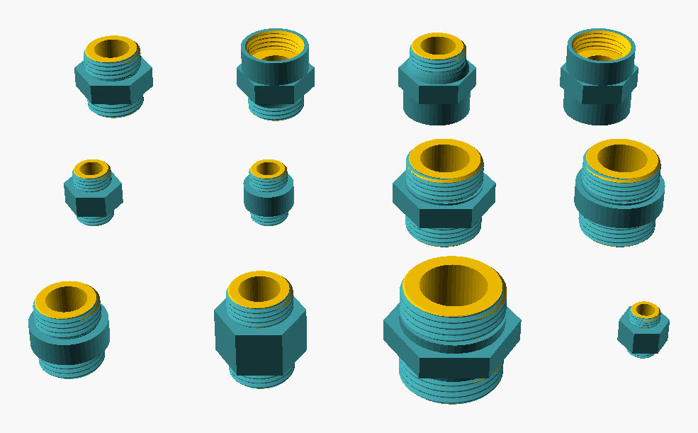
Figure 4: Straight (nipple-family) archetype gallery: twelve configurations of the BSPP straight fitting in a 4 × 3 grid, three-quarter view (still viewpoint lat 35°, lon 270°). The top row varies the four port-gender combinations at G1/2 (M × M nipple, M × F and F × M adapters, F × F socket — the female ends show the wider tapped mouth); the middle row crosses middle-band shape (hex wrench-grip vs round barrel) with size (G1/4, G3/4); the bottom row holds specials (round G1/2 barrel, a long unthreaded middle band, the larger G1, and the smallest G1/8). Gender varies along one axis and size/shape along the others, so the gallery shows the gender facet (F-02) as orthogonal to the dimensional facets — the same straight body recurs male- or female-ported.
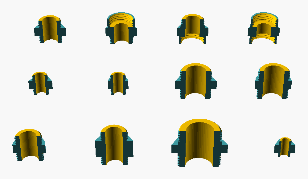
Figure 5: Straight archetype cutaway companion: the same twelve configurations as fig:straight-archetypes, each sectioned on its mid-plane (BOSL2 BACK cutaway) so the camera looks into the bore. The cut exposes the axial through-bore running the length of each fitting, its diameter scaling with nominal size; in the female-ported cells of the top row the tapped socket is recessed into the end face, while the male ends taper to the external thread.
The straight facet carries a second configuration beside the
nipple family: bsppfit_pipe(), a length of pipe of a given
overall length with an independently gendered port at each end (see
the Library Overview). Where the nipple
is a short connector defined by its thread lengths, the Pipe is a
long run of plain round stock defined by its length — the two are
the short and long limits of the same two-port straight body. The
Pipe has its own archetype gallery (variant gallery-archetypes,
with a sectioned gallery-archetypes-cut companion) sweeping the
four port-gender combinations against length and size. Topologically
the nipple and the Pipe are the same object — a two-port tube —
which is the starting observation of the Topological Foundations part below.
The Pipe archetypes are shown in 6, sectioned in
7.
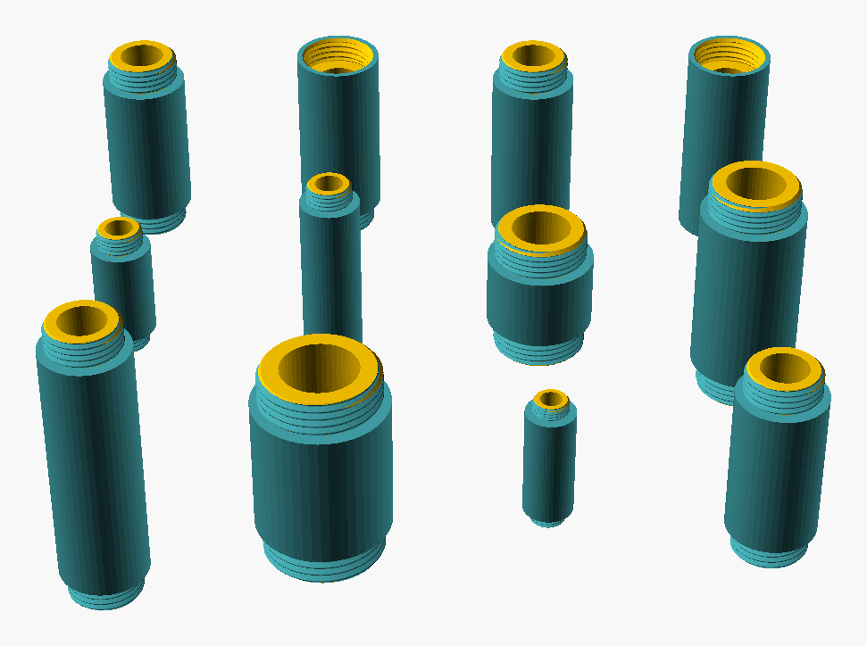
Figure 6: Pipe archetype gallery: twelve configurations of bsppfit_pipe() in a 4×3 grid — the top row sweeps the four port-gender combinations (M×M, M×F, F×M, F×F) at G1/2, the middle row crosses length with size, and the bottom row holds specials (a long run, a larger size, the smallest size, a thick-wall variant). The Pipe is the long-run limit of the straight facet, distinct from the short-connector Nipple of 4.
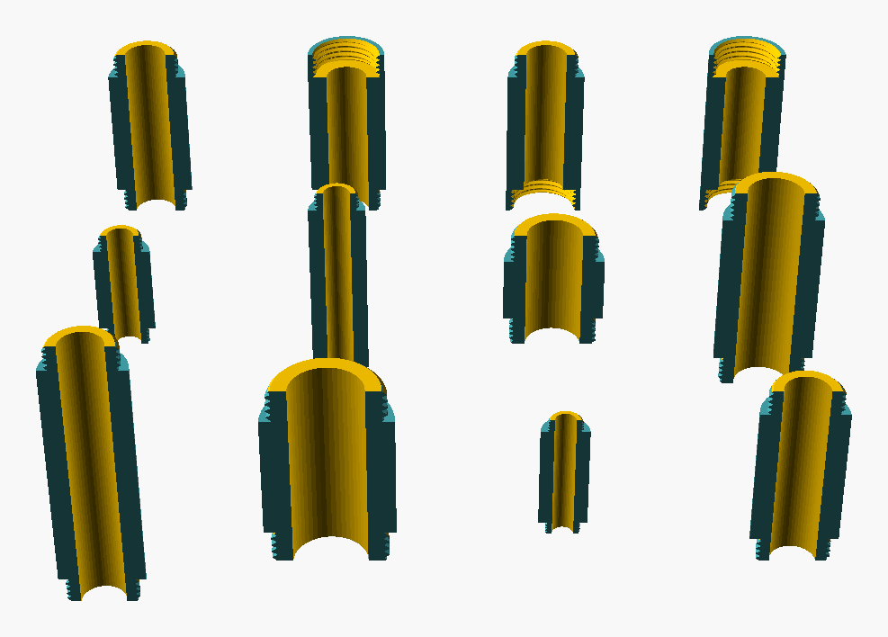
Figure 7: Pipe archetype cutaway companion: the same twelve configurations as 6, each sectioned on its mid-plane (BOSL2 BACK cutaway) so the through-bore is visible. The bore runs the full length; male ends carry the external thread at the tip, female ends a tapped socket recessed into the end face. The thick-wall cell shows a visibly narrower bore.
4.2. G-02 — Elbow
Elbow — two ports at an angle. Subtypes: 90°, 45°, male × male, female × female, male × female. Equal or reducing. The configuration space — gender × size × dimensional specials — is shown in 8, with the internal swept-bend bore in 9.
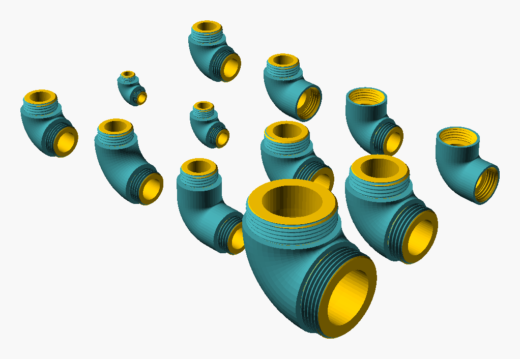
Figure 8: Elbow archetype gallery: twelve configurations of the BSPP elbow in a 4 × 3 grid, three-quarter view (still viewpoint lat 30°, lon 315°). The back row varies the four port-gender combinations (M × M, M × F, F × M, F × F — the mixed forms are "street" elbows); the middle row sweeps nominal size (G1/8, G1/4, G3/4, G1); the front row holds dimensional specials (default G1/2, long-radius bend, long arms, and the largest G1½, foreground). Gender varies along one axis and size along another, so the gallery shows the gender facet (F-02) as orthogonal to the dimensional facets — the same bend geometry recurs male- or female-ported.
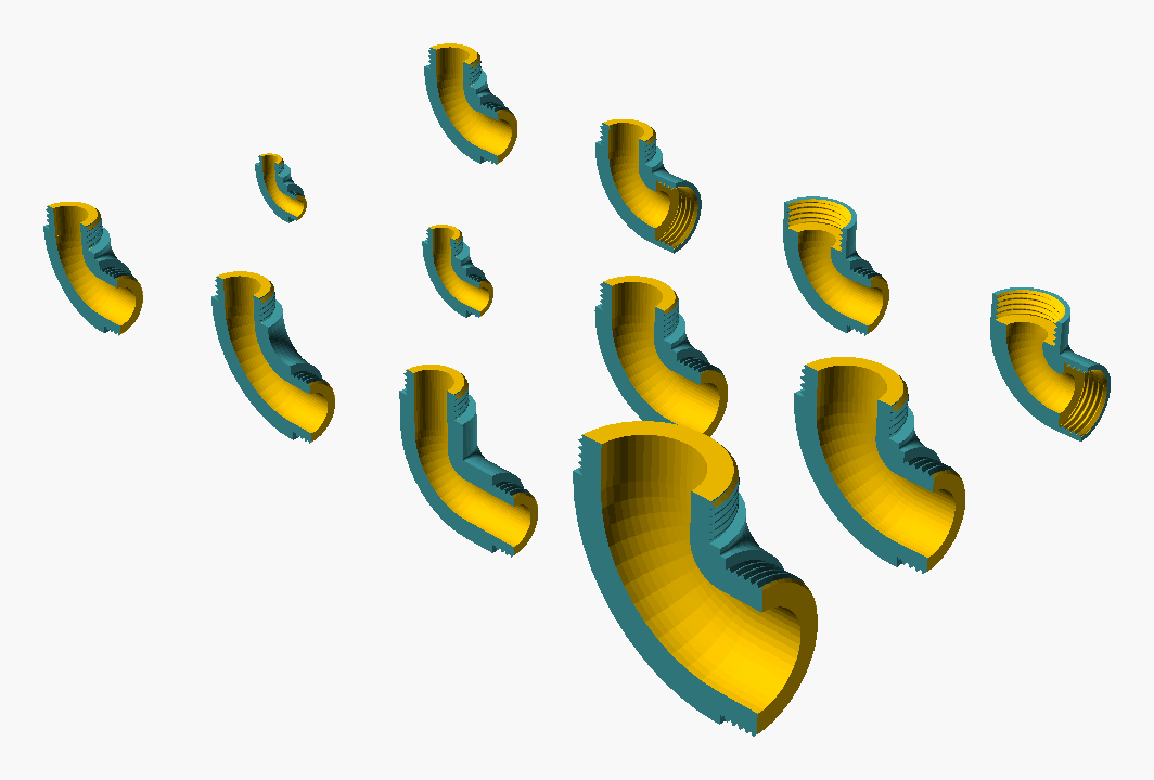
Figure 9: Elbow archetype cutaway companion: the same twelve configurations as fig:elbow-archetypes, each sectioned on its mid-plane (BOSL2 BACK cutaway) so the camera looks into the bore. The cut exposes the through-bore following the swept bend — a quarter-torus joining the two straight arm bores — and, in the female-ported cells of the back row, the tapped socket recessed into the arm end face.
4.3. G-03 — Tee
Tee (configuration of G-10 Manifold) — three ports,
T-shaped. A configuration of G-10 Manifold, not a
separate geometry class: the tee is the branch_count = 1
configuration of the unified branch-fitting class. Subtypes (equal tee, reducing
tee) are recovered by setting size_run and size_branch
independently on Manifold(). The trade name tee is
preserved here as a configuration label; for the geometric
description see G-10. Illustrated as the first cell of the
Manifold archetype galleries: 22 (solid)
and 23 (section).
4.4. G-04 — Cross
Cross (configuration of G-10 Manifold) — four
ports, +-shaped. A configuration of G-10 Manifold, not a
separate geometry class: the cross is the branch_count = 1,
branch_sides = "both" configuration of the unified
branch-fitting class. The trade name cross is preserved
here as a configuration label; for the geometric
description see G-10. Illustrated as the second cell of the
Manifold archetype galleries: 22 (solid)
and 23 (section).
4.5. G-05 — Reducer
Reducer — changes nominal size. Concentric (same axis) or eccentric (offset; drains better in horizontal lines). The configuration space — gender × body shape × concentric/eccentric subtype — is shown in 10, with the internal conical size transition in 11.
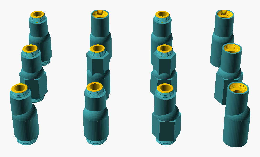
Figure 10: Reducer archetype gallery: twelve configurations of the BSPP reducer in a 4 × 3 grid, three-quarter view (still viewpoint lat 35°, lon 270°). The top row varies the four port-gender combinations (M × M reducer, M × F reducing bushing, F × M reverse bushing, F × F reducing coupler); the middle row applies a wrench-grip hex body to the large port, the small port, both ports, and (last cell) hex-large combined with F × F gender to show hex body and gender are orthogonal; the bottom row holds eccentric subtypes (offset LEFT, offset BACK, eccentric combined with hex-large, and eccentric combined with F × F gender). The same conical reducing body recurs across gender, body shape, and offset, so the gallery shows those facets as mutually orthogonal.
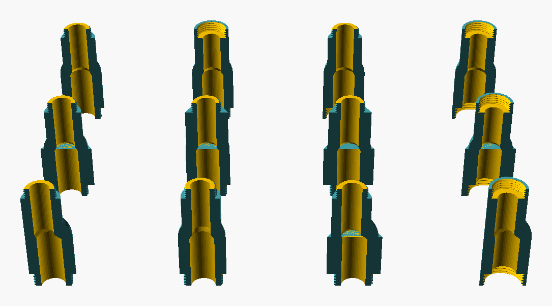
Figure 11: Reducer archetype cutaway companion: the same twelve configurations as fig:reducer-archetypes, each sectioned on its mid-plane (BOSL2 BACK cutaway) so the camera looks into the bore. The cut exposes the conical size transition — the wide bore stepping down to the narrow bore — and, in the bottom-row eccentric cells, the offset bore path where the small-port axis is displaced from the large-port axis. The hex-body cells show the wall thickness carried around the round bore.
4.6. G-06 — Cap and plug
Cap and plug — terminates a port. Cap goes over
a male thread; plug goes into a female thread. This is the one
geometry facet realised by two modules
(bsppfit_cap(), bsppfit_plug()), a cap-and-plug pair. The
cap's configuration space — size × head shape × head height —
is shown in 12, with its internal female thread in
13; the plug's — size × head shape × thread
length — in 14, with its solid male shaft in
15. The cutaways make the cap/plug duality
concrete: the cap is hollow (female bore the male port enters),
the plug is solid (male shaft entering a female port).
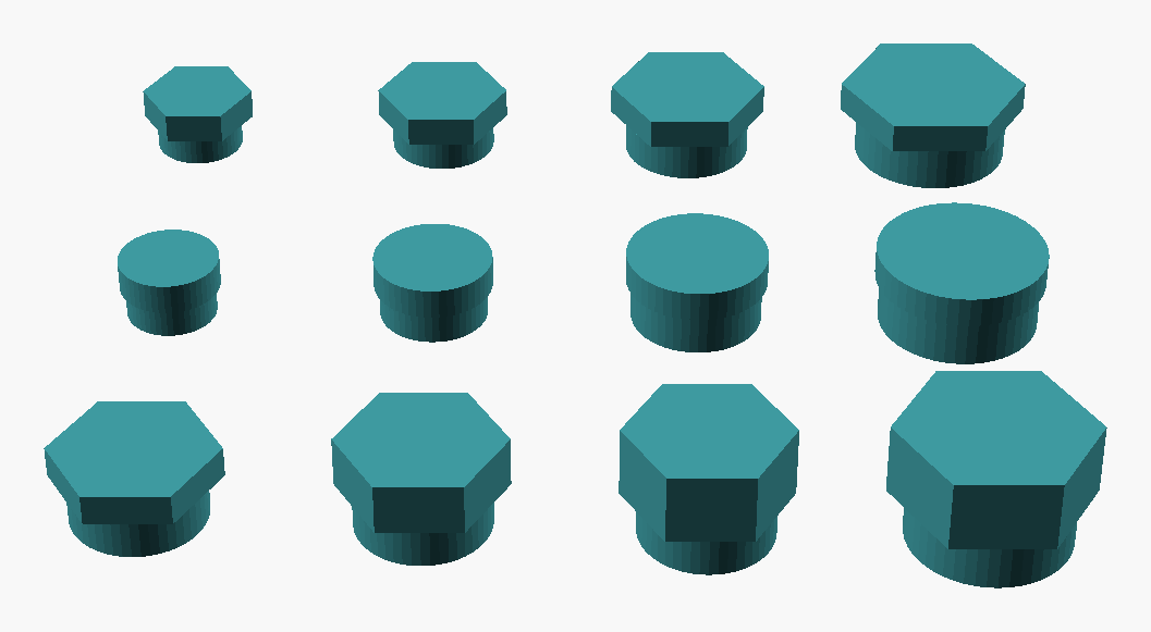
Figure 12: Cap archetype gallery: twelve configurations of the BSPP cap in a 4 × 3 grid, three-quarter view (still viewpoint lat 35°, lon 270°). The top row sweeps size with a hex head (G1/4, G3/8, G1/2, G3/4); the middle row repeats those sizes with a round head; the bottom row holds head-height variations on the hex G1/2 (default 6 mm, 10 mm, 14 mm) plus a larger G3/4 with a 14 mm head. Size varies along one axis and head shape/height along the others, so the gallery shows those facets as orthogonal. The cap presents no thread externally — the female thread is internal (see the cutaway).
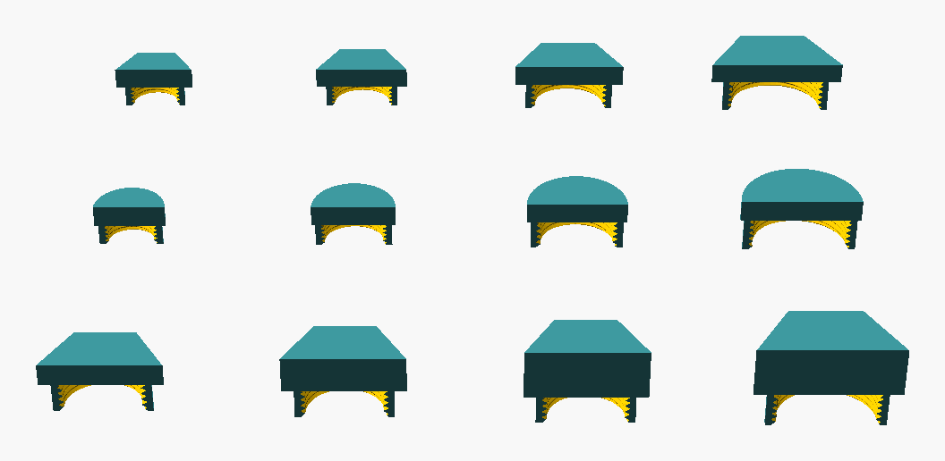
Figure 13: Cap archetype cutaway companion: the same twelve configurations as fig:cap-archetypes, each sectioned on its mid-plane (BOSL2 BACK cutaway) so the camera looks into the head. The cut exposes the internal female thread the cap screws over, and the head's solid wall thickness around that bore; the bottom-row head-height variations show the cavity deepening.
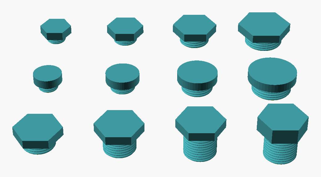
Figure 14: Plug archetype gallery: twelve configurations of the BSPP plug in a 4 × 3 grid, three-quarter view (still viewpoint lat 35°, lon 270°). The top row sweeps size with a hex head (G1/4, G3/8, G1/2, G3/4); the middle row repeats those sizes with a round head; the bottom row sweeps the male thread length on a hex G1/2 (default, 14 mm, 20 mm) plus a 20 mm thread with a taller 10 mm head. The external male thread that screws into the mating socket is visible below each head.
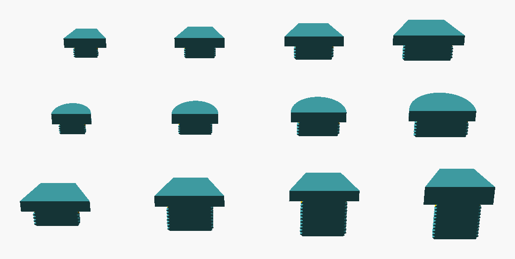
Figure 15: Plug archetype cutaway companion: the same twelve configurations as fig:plug-archetypes, each sectioned on its mid-plane (BOSL2 BACK cutaway). Unlike the cap, the plug has no internal bore: the cut shows the solid head and the solid threaded shaft in cross-section (the male thread profile on the cut edge). The bottom-row thread-length variations show the solid shaft lengthening. This solid-versus-hollow contrast with fig:cap-archetypes-cut is the geometric distinction between plug and cap.
4.7. G-07 — Union
Union — detachable joint, three-piece (two halves plus collar nut), allows disassembly without rotating the whole pipe. The configuration space — pose (assembled vs exploded) × pipe-end gender × the single component pieces — is shown in 16, with the internal conical seat (the sealing geometry that is invisible from outside) in 17.
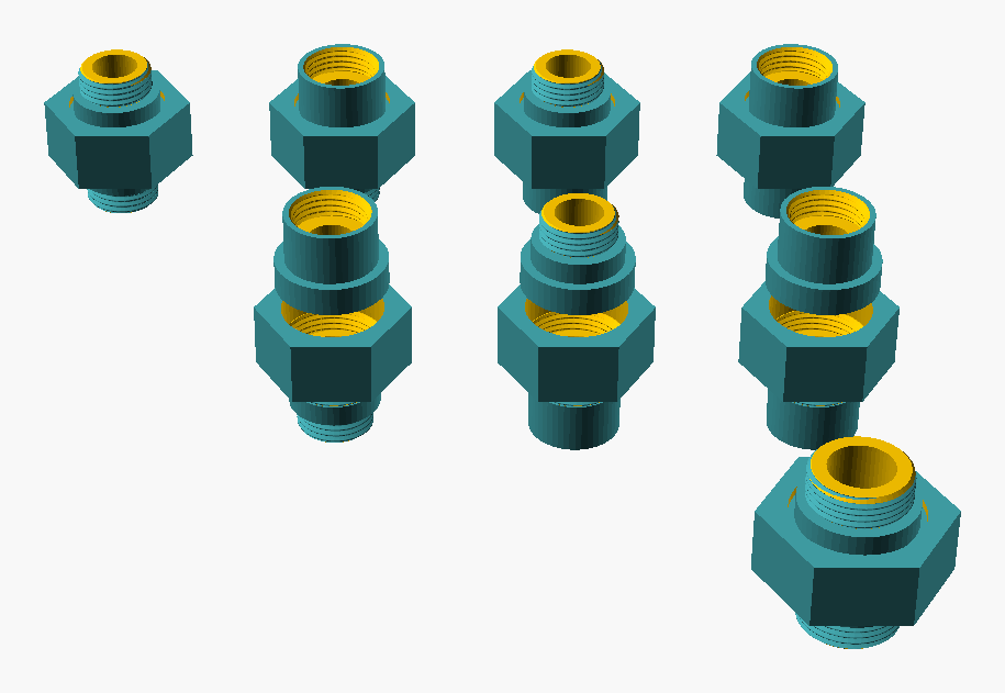
Figure 16: Union archetype gallery: twelve configurations of the BSPP union in a 4 × 3 grid, three-quarter view (still viewpoint lat 35°, lon 270°). The top row shows the assembled union in the four pipe-end gender combinations (M × M, M × F, F × M, F × F) at G1/2. The middle row repeats those combinations exploded along the axis, separating the three pieces (tail A, tail B, collar nut) to reveal the construction — the assembled/exploded mirror between rows 1 and 2 is a direct A/B comparison. The bottom row holds the single component pieces (tail A, tail B, the collar nut) plus a larger G3/4 assembled union for scale.
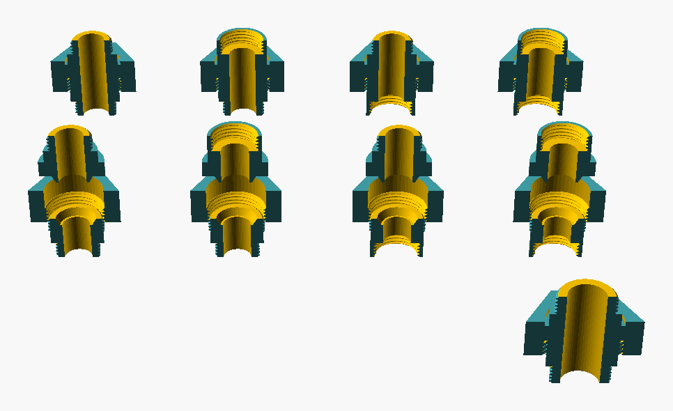
Figure 17: Union archetype cutaway companion: the same twelve configurations as fig:union-archetypes, each sectioned on its mid-plane (BOSL2 BACK cutaway) so the camera looks into the bore. The cut exposes what makes a union a union: the internal conical seat where tail A meets tail B (the sealing surface, invisible from outside), the bore continuity through the joint, and the coupling thread between the collar nut and tail B. The exploded cells (middle row) section all three pieces at once; the single-piece cells (bottom row) show each component's internal geometry, including the nut's internal coupling thread.
4.8. G-08 — Hex bush
Hex bush (reducing bush) — short fitting that reduces from larger external thread to smaller internal thread. The configuration space — gender layout (M-large vs F-large) × size ratio × hex height — is shown in 18, with the through-bore and the diameter step at the gender transition in 19.
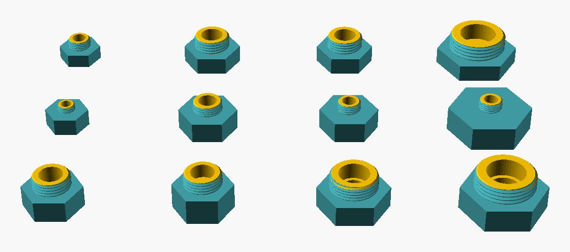
Figure 18: Hex-bush archetype gallery: twelve configurations of the BSPP reducing bush in a 4 × 3 grid, three-quarter view (still viewpoint lat 35°, lon 270°). The top row holds the standard M-large layout sweeping the size ratio (G1/4 × G1/8, G1/2 × G3/8, G1/2 × G1/4, G1 × G1/4 extreme step). The middle row mirrors those size pairs in the gender-swapped F-large layout, showing the model's symmetry between the two layouts. The bottom row holds specials: an equal-size gender-changer (neither port reducing), a tall-hex variant for extra wrench grip, and two mid-range commercial sizes. The male thread protrudes from each hex body; the female socket bore is visible within it.
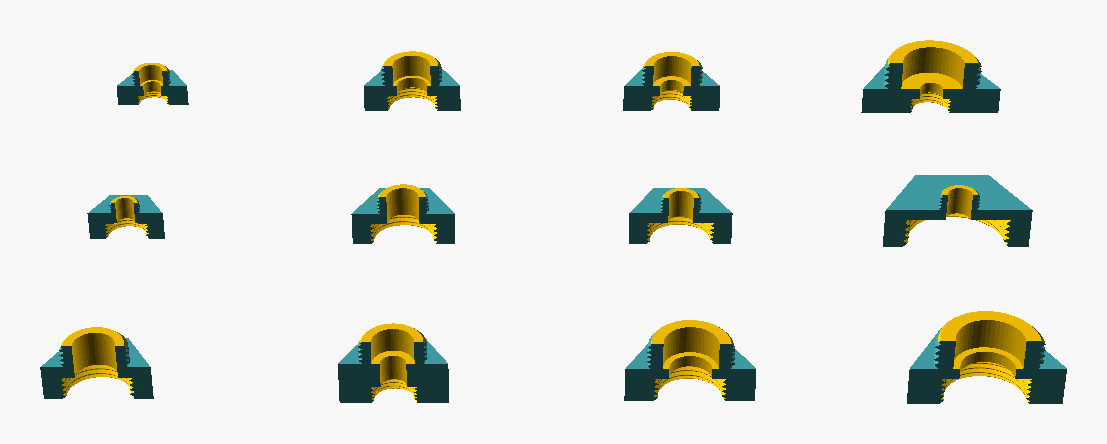
Figure 19: Hex-bush archetype cutaway companion: the same twelve configurations as fig:hexbush-archetypes, each sectioned on its mid-plane (BOSL2 BACK cutaway) so the camera looks into the bore. The cut exposes the through-bore passage from the male thread to the female socket and the diameter step at the gender transition — the geometric essence of a reducing bush. The M-large (top) and F-large (middle) rows show the step in opposite senses, making the gender symmetry concrete.
4.9. G-09 — Hose tail
Hose tail (barb) — threaded fitting on one side, serrated barb on the other for hose attachment. The configuration space — barb profile × body shape × gender × barb count — is shown in 20, with the through-bore and the barb profile in section in 21.
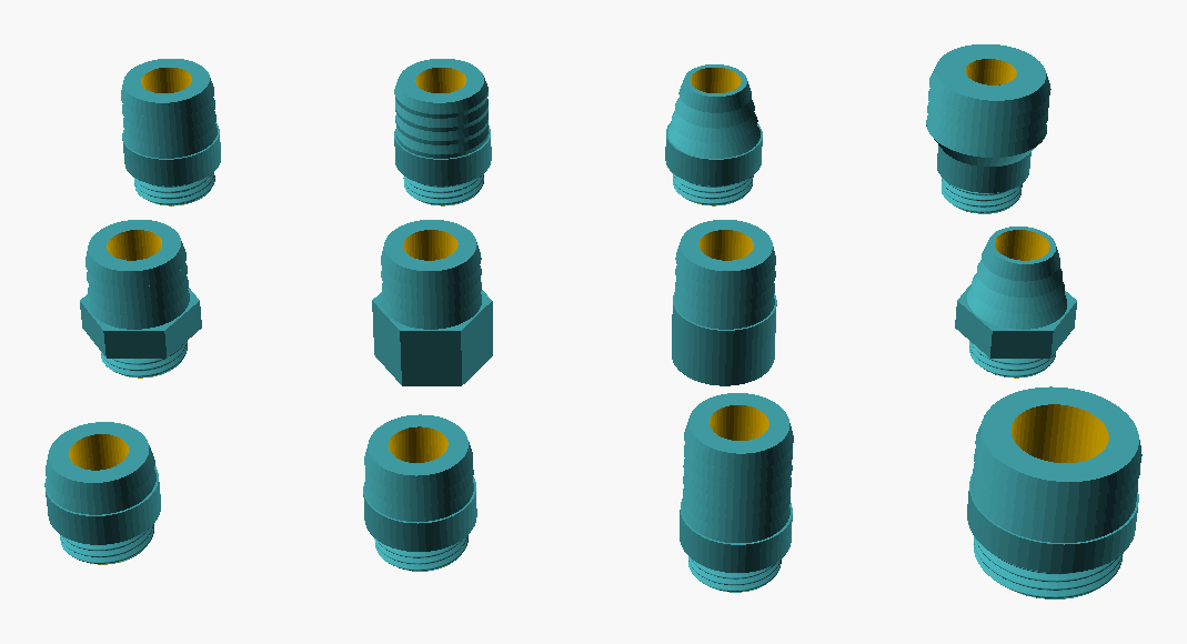
Figure 20: Hose-tail archetype gallery: twelve configurations of the BSPP hose tail in a 4 × 3 grid, three-quarter view (still viewpoint lat 35°, lon 270°). The top row varies the barb profile on a round male body (shark-fin default, stepped, christmas-tree) and ends with a shouldered form (barbs wider than the body). The middle row crosses body shape with gender (hex male, hex female, round female, hex christmas-tree). The bottom row sweeps barb count (2, 3, 6) and ends with a larger G1 size. The threaded end (bottom of each cell) and the barbed hose end (top) share one axis; the barb serrations are most legible in the cutaway companion.
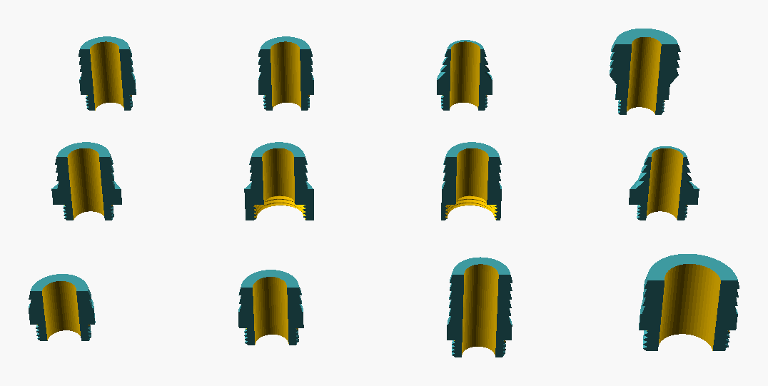
Figure 21: Hose-tail archetype cutaway companion: the same twelve configurations as fig:hosetail-archetypes, each sectioned on its mid-plane (BOSL2 BACK cutaway) so the camera looks into the bore. The cut exposes the through-bore running the length of the fitting and — the point of the cutaway for this model — the barb wall profile in section (the shark-fin, stepped, and christmas-tree serrations read clearly on the cut edge where they are hard to distinguish on the solid exterior at grid scale). The female-ported cells of the middle row show the tapped socket interior.
4.10. G-10 — Manifold
Manifold — the unified branch-fitting class. A straight cylindrical run carrying one or more branch ports perpendicular to the run, plus a port at each end of the run. The trade categories tee, cross and manifold are all the same pipe-bodied geometry varying only in branch count and branch arrangement; they are recovered as configurations of this single class:
- Tee
branch_count = 1, branch_sides = "one"— three ports (two run ends + one branch).- Cross
branch_count = 1, branch_sides = "both"— four ports (two run ends + two opposed branches).- Manifold
branch_count >= 2— the multi-branch distribution forms.
In every configuration the run ends and the branches take
per-port genders and sizes; the run may be open or capped
at each end. History. Tee, Cross, and Manifold were
originally three separate geometry classes; the continuum
was found to be geometric rather than merely descriptive,
and they were unified into this single class, with G-03
and G-04 retained only as configurations of G-10 and
their model files marked deprecated. Non-orthogonal
(Y-form) branches are supported via the
branch_angle parameter (range 30..150 degrees,
perpendicular at 90); all branches lean by the same
angle (uniform tilt). The symmetric Y-fan form, where
branches splay apart from a common stem, requires per-
branch tilt and is a planned later enhancement.
Distinction from a pneumatic distribution block —
a solid rectangular
bar with tapped ports — is deliberate: that is a
different product family, not modelled here; G-10 covers
the pipe-bodied form shown in supplier catalogues (HTC /
PVC-Welt AV-810/820/830/850 and equivalents).
The configuration range — branch count and arrangement (recovering tee and cross), branch lean angle (Y- and X-forms), per-port gender, and capped/pointed run ends — is shown in 22, with the run bore and the branch-to-run junctions in 23. Because tee (G-03) and cross (G-04) are configurations of this class, these two galleries are where the Tee and Cross are illustrated: the first two cells of each figure are the tee (one branch) and the cross (one branch each side), so no separate G-03 or G-04 galleries exist.
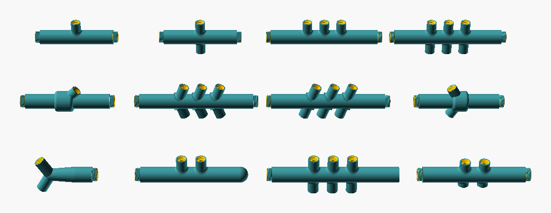
Figure 22: Manifold archetype gallery: twelve configurations of the unified branch-fitting class in a 4 × 3 grid, three-quarter view (still viewpoint lat 35°, lon 270°). The top row shows the perpendicular basics — tee (one branch; this is the G-03 configuration), cross (one branch each side; the G-04 configuration), a three-branch rake, and a three-plus-three rake. The middle row shows leaning branches: a Y-tee at 45°, a parallel-lean rake at 70°, an X-form (top 70°, bottom 110°, opposite lean), and a Y-fan with stem at 120°. The bottom row shows a left-pointed Y-piece, a capped-end two-branch, a mixed-gender rake (male and female branches and run ends), and asymmetric branch-arm lengths. The single pipe-bodied geometry recovers tee, cross, and manifold by branch count and arrangement alone.
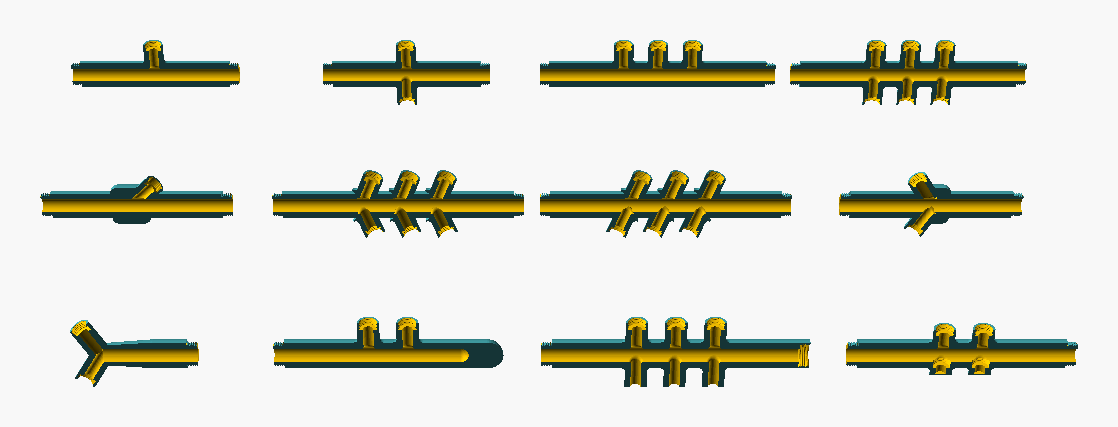
Figure 23: Manifold archetype cutaway companion: the same twelve configurations as fig:manifold-archetypes, each sectioned on its mid-plane (BOSL2 BACK cutaway) so the camera looks into the bore. The cut exposes the run bore and — the defining feature of the class — the branch-to-run junctions, where each branch bore opens into the common run bore. The leaning cells show the junction at the branch angle; the capped-end cell shows the wall closing the run; the asymmetric-arms cell shows the branch bores at different lengths. Tee (first cell) and cross (second cell) are the G-03 and G-04 configurations seen in section.
5. Facet — Gender (F-02)
Gender describes which end of a fitting carries the male (external) thread and which carries the female (internal) thread. It is the most basic compatibility check between two fittings: a male thread mates with a female thread of the matching form and size.
At the geometry level the distinction is simply where the thread sits: 24 places a male fitting beside a female fitting of the same size and family — the male carries its thread on the outside, the female on the inside of its bore. The cutaway companion, 25, shows this in section: the male's bore wall is plain and the thread is external; the female's thread runs along the inside of the bore.
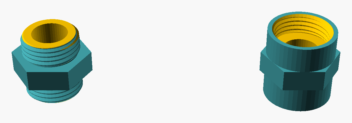
Figure 24: Gender at the geometry level: a male fitting (left) and a female fitting (right) of the G-01 straight family, same size (G1/2) and hex body, so gender is the only difference. The male carries its thread externally; the female carries it internally (the tapped bore). This complements the thread-level explanation below.
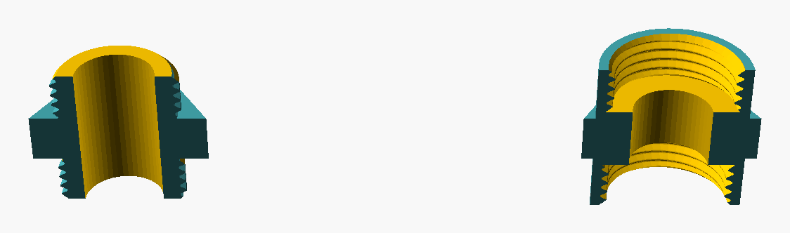
Figure 25: Gender comparison, cutaway companion: the same male (left) and female (right) fittings sectioned on the mid-plane (BOSL2 BACK cutaway). The male fitting has a plain through-bore with the thread on the outside; the female fitting carries the thread on the inside of the bore, running its full length. The internal-versus-external thread placement is the geometric essence of the gender distinction.
5.1. Values
- Male (M)
- external thread, smaller bore at the threaded end.
- Female (F)
- internal thread, larger bore at the threaded end.
- Mixed
- a fitting carries male on one port and female on another. Example: a male × female elbow.
5.2. Conventions and notation
The two-port shorthand "M × F" or "F × F" indicates the
gender of each port. For three-port fittings (tees), all three
ports are usually the same gender (typically female).
Manufacturer catalogues sometimes use MF as a single token
for "male × female".
Port order in shorthand is conventional but not standardised: for an elbow, "male × female" usually means the inlet is male and the outlet is female, but this should be confirmed visually before purchase.
5.2.1. What "inlet" and "outlet" mean here
Inlet is the port through which the working fluid enters the fitting; outlet is the port through which it leaves. The labels are tied to flow direction, not to a fixed end of the fitting.
The distinction matters in three ways:
- Direction-sensitive devices. A check valve, a regulator, a strainer, or a one-way ball valve will only function correctly if installed with the labelled inlet upstream. An arrow stamped on the body usually disambiguates; respect it.
- Asymmetric gendered fittings. For an "M × F" elbow, the inlet/outlet labelling determines which side carries the male thread (typically meeting an upstream female fitting) and which carries the female (typically meeting a downstream male fitting or appliance). Reversing the orientation works mechanically but reverses the gender sequence further down the line.
- Tool access during installation. "Inlet" and "outlet" sometimes correspond to accessible and buried ports. For a fitting to be tightened in place, at least one hexagonal flat must be reachable by a spanner; the orientation that puts the spanner-accessible port on the visible side may be forced by tool access rather than by flow.
Symmetric fittings (equal tee with all three ports female, straight nipple, equal coupling) have no intrinsic inlet or outlet; the user assigns them per the installation.
5.3. Constraints
- A single port cannot be both male and female.
- A male × male fitting (nipple) cannot self-mate; it requires two female-port mating fittings (sockets, valves, etc.).
- In confined spaces, gender choice may be forced by the orientation of adjacent fixed fittings (the user does not pick the gender; the existing assembly does).
5.4. Common selection errors
- Buying two fittings of the same gender for a joint that needs opposing genders. Usually obvious on inspection; occasionally hidden when both fittings ship in covered packaging.
- Confusing Rp (BSPT female parallel) with Rc (BSPT female taper) at the same nominal designation. Both are "female" but seal differently.
6. Facet — Nominal Size (F-04)
Nominal size names a fitting by its bore (the inside diameter of the pipe it connects to), not by its thread outer diameter. This is a frequent source of confusion for users used to thread-OD-based naming.
6.1. Conventions
- The size is given in inches even in metric countries; this is a historical fixture of the BSP family.
- Common sizes (smallest to largest):
1/8",1/4",3/8",1/2",3/4",1",1 1/4",1 1/2",2",2 1/2",3",4". Domestic plumbing rarely exceeds1". - The actual thread OD for a given nominal size is larger
than the nominal value. For example,
G1/2has a thread OD of approximately 20.96 mm;G1has a thread OD of approximately 33.25 mm. ISO 228-1 specifies the exact dimensions.
6.2. Implications for selection
- Two fittings of the same nominal size and same thread form mate by design. Mating two different nominal sizes is handled with a reducer (G-05) or a hex bush (G-08).
- A fitting marked "1/2" without thread-form context is
ambiguous: it could be
G1/2(BSPP),R1/2(BSPT), or1/2 NPT. The thread-form designation is part of the size specification, not a separate dimension.
6.3. Common selection errors
- Reading "1/2 inch BSP" off a tap and assuming the thread OD
is 1/2 inch. The user then sources a fitting designed for
G3/8(whose thread OD is around 16.66 mm, closer to 1/2 inch). The fittings will not mate. - Confusing nominal size with pipe schedule (wall thickness
class). These are independent: a
1/2"pipe can be schedule 40 or schedule 80, with the same nominal size and outer diameter but different bore.
6.4. Bore and thread-OD notation (15/21, 20/27, …)
In France and parts of continental Europe, BSPP fittings are
commonly designated by a pair of millimetre values rather
than by the inch fraction — for example 15/21 for what
ISO calls G1/2, or 20/27 for G3/4.
The two numbers are:
- the nominal bore in millimetres (the historical inside diameter of the iron pipe the fitting was sized for), followed by
- the nominal external thread diameter in millimetres, rounded to the nearest whole millimetre.
So 15/21 describes a fitting whose pipe bore is nominally 15 mm and whose male thread is nominally 21 mm in outer diameter. The exact thread OD per ISO 228-1 is 20.96 mm; the 21 in the European designation is that value rounded.
This makes the European notation more concrete than the inch-fraction form: both numbers are in real millimetres that the user can measure, while 1/2 alone refers to neither bore nor thread OD exactly. The two notations name the same thread; the choice between them is regional, not technical.
Equivalence between the two notations for the most common sizes:
| ISO | French | Bore (mm) | Thread OD (mm) |
|---|---|---|---|
| G1/8 | 6/12 | 6 | 9.73 |
| G1/4 | 8/13 | 8 | 13.16 |
| G3/8 | 12/17 | 12 | 16.66 |
| G1/2 | 15/21 | 15 | 20.96 |
| G3/4 | 20/27 | 20 | 26.44 |
| G1 | 26/34 | 26 | 33.25 |
| G1 1/4 | 33/42 | 33 | 41.91 |
| G1 1/2 | 40/49 | 40 | 47.80 |
| G2 | 50/60 | 50 | 59.61 |
Note: the rounded "second number" in the French form (12, 13, 17, 21, …) is thread OD rounded, not bore. Reading 15/21 as "15 inside, 21 outside (of the pipe)" is a common but incorrect mental model: the 21 is the male thread OD, not the pipe wall OD.
6.5. Per-size dimension reference (BSPP, BSPT, NPT)
The dimension tables below give the standardised geometry of BSPP, BSPT, and NPT threads at the sizes commonly encountered in plumbing, pneumatic, and light-hydraulic service. Values are drawn from the relevant standards (ISO 228-1 for BSPP, ISO 7-1 for BSPT, ANSI/ASME B1.20.1 for NPT) and rounded to two decimals where the standard gives more precision.
What the columns mean.
- Pitch
- the axial distance between adjacent thread crests. Often quoted as threads per inch (TPI), the reciprocal of pitch in inches. Both forms are given.
- Major OD
- the diameter measured across the crests of the male thread. For BSPP this is constant along the length; for BSPT/NPT it is measured at the gauge plane (a defined position along the taper, near the start of the threaded section).
- Minor diameter
- the diameter measured across the thread roots of the male (equivalently, across the crests of the female). Useful for stress calculation and for visually distinguishing similar sizes.
- Useful thread length
- the typical effective thread engagement length for a hand-tight assembly, before any wrench-tightening allowance. Indicative; manufacturer catalogues vary.
6.5.1. BSPP (ISO 228-1)
BSPP is a parallel thread; the major and minor OD are constant along the threaded length.
| Size | TPI | Pitch (mm) | Major OD (mm) | Minor OD (mm) | Thread len. (mm) |
|---|---|---|---|---|---|
| G1/8 | 28 | 0.91 | 9.73 | 8.57 | 4.0 |
| G1/4 | 19 | 1.34 | 13.16 | 11.45 | 6.0 |
| G3/8 | 19 | 1.34 | 16.66 | 14.95 | 6.4 |
| G1/2 | 14 | 1.81 | 20.96 | 18.63 | 8.2 |
| G3/4 | 14 | 1.81 | 26.44 | 24.12 | 9.5 |
| G1 | 11 | 2.31 | 33.25 | 30.29 | 10.4 |
| G1 1/4 | 11 | 2.31 | 41.91 | 38.95 | 12.7 |
| G1 1/2 | 11 | 2.31 | 47.80 | 44.85 | 12.7 |
| G2 | 11 | 2.31 | 59.61 | 56.66 | 15.9 |
6.5.2. BSPT (ISO 7-1)
BSPT is tapered at 1:16. The values below are at the gauge plane, the reference position along the taper where thread engagement is normally measured.
| Size | TPI | Pitch (mm) | OD, gauge (mm) | Thread len. (mm) |
|---|---|---|---|---|
| R1/8 | 28 | 0.91 | 9.73 | 6.5 |
| R1/4 | 19 | 1.34 | 13.16 | 9.7 |
| R3/8 | 19 | 1.34 | 16.66 | 10.1 |
| R1/2 | 14 | 1.81 | 20.96 | 13.2 |
| R3/4 | 14 | 1.81 | 26.44 | 14.5 |
| R1 | 11 | 2.31 | 33.25 | 16.8 |
| R1 1/4 | 11 | 2.31 | 41.91 | 19.1 |
| R1 1/2 | 11 | 2.31 | 47.80 | 19.1 |
| R2 | 11 | 2.31 | 59.61 | 23.4 |
The thread profile (55° Whitworth) and the pitch are the same as BSPP at the same nominal size; only the parallel- versus-tapered geometry differs. This is what makes the BSPP × BSPT confusion (see SC-04) possible: the thread shape on each fitting matches the other, only the along-the-thread geometry betrays the mismatch.
6.5.3. NPT (ANSI/ASME B1.20.1)
NPT is tapered at 1:16 like BSPT, but with a 60° profile (vs Whitworth 55°). The values below are at the pitch line at the reference plane.
| Size | TPI | Pitch (mm) | OD, pitch (mm) | Thread len. (mm) |
|---|---|---|---|---|
| 1/8 NPT | 27 | 0.94 | 9.51 | 6.7 |
| 1/4 NPT | 18 | 1.41 | 12.61 | 10.2 |
| 3/8 NPT | 18 | 1.41 | 16.07 | 10.4 |
| 1/2 NPT | 14 | 1.81 | 19.96 | 13.6 |
| 3/4 NPT | 14 | 1.81 | 25.45 | 14.0 |
| 1 NPT | 11.5 | 2.21 | 31.92 | 17.3 |
| 1 1/4 NPT | 11.5 | 2.21 | 40.61 | 17.9 |
| 1 1/2 NPT | 11.5 | 2.21 | 46.65 | 18.4 |
| 2 NPT | 11.5 | 2.21 | 58.43 | 19.2 |
Compare 1/2 NPT (TPI 14, OD 19.96 mm) with G1/2 BSPP (TPI 14, OD 20.96 mm): the same TPI but a different diameter. They appear to engage when held by hand, cross-thread, and damage one or both fittings. The 1-mm-diameter offset is what makes the BSPP × NPT confusion (see Mismatch consequences) more obviously wrong than BSPP × BSPT, which shares the diameter.
6.5.4. How to read the tables
- For mating, the relevant columns are TPI (must match) and Major OD or OD at gauge plane (must match, within manufacturing tolerance).
- For physical identification of an unknown male thread: measure the OD with a vernier caliper, count the threads in a known length, and look the pair up.
- For stress calculation under load, the Minor OD is the relevant cross-section.
- For ordering a tap or die: tap and die sizes are quoted
as the thread designation (
G1/2,R1/2,1/2 NPT); the pitch and OD do not need to be specified separately.
6.5.5. Sources and verification
- BSPP: ISO 228-1:2000, Pipe threads where pressure-tight joints are not made on the threads.
- BSPT: ISO 7-1:1994, Pipe threads where pressure-tight joints are made on the threads.
- NPT: ANSI/ASME B1.20.1-2013, Pipe threads, general purpose (inch).
The tables above are working references for the project; they are not a substitute for the standards. For safety-critical or pressure-rated applications consult the standards directly (or a manufacturer's certified data sheet).
7. Facet — Sealing Mechanism (F-05)
The sealing mechanism is the physical method by which the joint becomes leak-tight. It is determined primarily by the thread form (parallel vs tapered) and secondarily by the application context.
7.1. Mechanisms
- Bonded seal washer (Dowty seal)
a flat washer with a metal outer ring and a rubber inner bonded to it. Compresses between the male fitting's flange and the female face. Used with BSPP and other parallel-thread fittings. Typical service limit: 200 bar, depending on rubber compound.
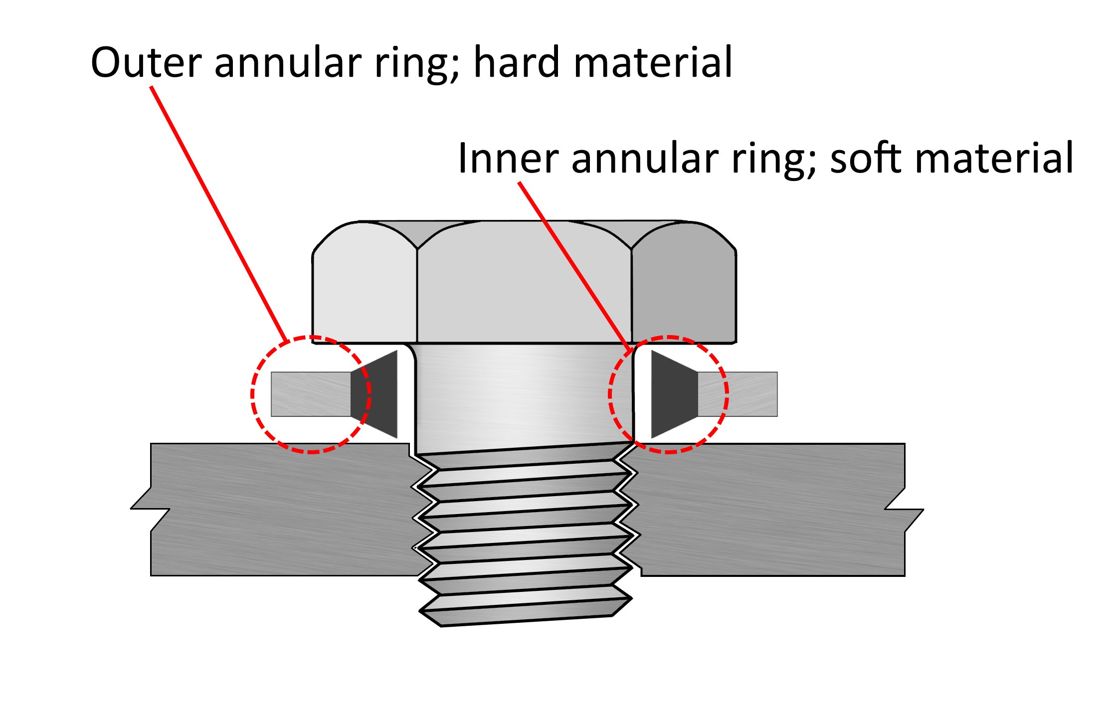
Figure 26: Cross-section of a bonded seal washer compressed under a hex-headed bolt. The outer hard annular ring (left callout) sets the compressed thickness and prevents the rubber from extruding under load; the inner soft annular ring (right callout) deforms to fill the surface asperities of both the bolt's underside and the tapped face, producing the seal. Diagram by Wikipedia user Brotherpete (created using Paint.net). Public domain, via Wikimedia Commons. See also Sources and Attributions.
- O-ring
- a circular elastomer ring seated in a groove on the male fitting's seat or under the head. Common in BSPP hydraulic fittings (e.g., banjo bolts). Typical service: varies by elastomer (NBR up to ~100 °C, FKM up to ~200 °C).
- PTFE tape
- thin polytetrafluoroethylene tape wrapped around male threads before assembly. Fills the helical gap and acts as both seal and lubricant. Used with BSPT, NPT, and combined sealing surfaces; not a substitute for a face seal on BSPP.
- Anaerobic pipe sealant
- liquid that polymerises in the absence of air and the presence of metal ions, filling thread gaps and locking the assembly. Used with BSPT and NPT, especially for gas service where PTFE tape is discouraged.
- Cone seat (60° / 24°)
a metal-to-metal seal where the male fitting has a conical end that beds against a matching female cone. Common in hydraulic high-pressure connections; less common in plumbing.
Illustration: pending. The available candidate images conflate cone-seat sealing with adjacent-but-distinct mechanisms; a clearer cross-section is still being sought.
- Gasket
a soft sacrificial part compressed between two mating faces to form the seal. The gasket deforms to fill the asperities of the two surfaces. Variants encountered in BSPP and adjacent fitting families:
- Soft (fibre, elastomer, PTFE)
- low-cost, used for cold water, room-temperature pneumatic, drainage. Not for steam or high-temperature service.
- Composite (graphite, graphite-with-metal-mesh)
- heat tolerant up to several hundred °C. Standard for steam, hot oil, exhaust.
- Solid soft metal (copper, aluminium, soft steel)
- single-use, crushed on first assembly. Used at very high pressure and at high temperature where neither elastomer nor composite suffices. Typically associated with flange or face-sealed fittings rather than threaded ones.
The flat-face crush case from earlier editions of this section is a soft-metal gasket; it is included here as one of the variants. A free-standing flat washer (such as a bonded seal) is also a kind of gasket but is listed separately above because the rubber-on-metal construction and the parallel-thread-only application are distinctive.
7.2. Sealing × thread form
| Thread form | Bonded washer | O-ring | PTFE tape | Anaerobic | Cone seat |
|---|---|---|---|---|---|
| BSPP | Yes | Yes | No (1) | No (1) | Sometimes |
| BSPT | No (2) | No (2) | Yes | Yes | No |
| NPT | No (2) | No (2) | Yes | Yes | No |
(1) Tape and anaerobic compounds do not seal a parallel thread, regardless of how much is applied. The taxonomy lists them with BSPP only when used as auxiliary thread lubricants, never as the primary seal.
(2) Face seals do not work on tapered threads: there is no flat face to seat against, and the tapered thread engagement already does the sealing.
7.3. Common selection errors
- Wrapping PTFE tape on a BSPP fitting and expecting it to seal. The fitting tightens but seeps. The user rewraps, re-tightens, and damages the threads. The cure is a bonded seal washer or O-ring; the tape was the wrong mechanism, not the wrong amount.
- Using a bonded washer on a BSPT joint. The washer is compressed but the tapered geometry leaves gaps along the threads; the joint leaks.
- Reusing an O-ring after disassembly. Even an undamaged O-ring takes a compression set that may not re-seal at the same torque.
8. Facet — Material (F-06)
8.1. Common materials
- Brass
- the dominant material for domestic and light industrial BSPP fittings. Easily machined, corrosion resistant in clean water service, available in dozens of manufactured forms. Standard alloys: CW617N (CZ132, dezincification-resistant: DZR brass) for potable water, CW614N (CZ121) for general use.
- Nickel-plated brass
- brass with a thin nickel coating for cosmetic finish and additional corrosion resistance. Otherwise behaves as brass.
- Stainless steel
- 304 (general), 316 (marine, chemical service). Higher cost, higher pressure rating, broader chemical compatibility. Required for salt-water exposure and most food-grade applications.
- Plain (carbon) steel
- black or galvanised. Used for industrial steam, gas, and high-pressure water service. Susceptible to corrosion in wet service unless galvanised or coated.
- Plastic (PP, PVC, CPVC, nylon)
- low-pressure water, irrigation, drainage. PP is hot-water-capable; PVC is cold-water; CPVC is hot-water; nylon for compressed-air service at moderate pressure.
8.2. Compatibility with media
| Material | Cold water | Hot water | Steam | Air | Oil | Gas | Salt water |
|---|---|---|---|---|---|---|---|
| Brass (DZR) | Yes | Yes | Limited | Yes | Yes | Yes(*) | No |
| Stainless 304 | Yes | Yes | Yes | Yes | Yes | Yes | Limited |
| Stainless 316 | Yes | Yes | Yes | Yes | Yes | Yes | Yes |
| Galvanised st. | Yes | Yes | Yes | Yes | Yes | Yes | No |
| PP | Yes | Yes | No | Limited | No | No | Yes |
| PVC | Yes | No | No | No | No | No | Yes |
(*) Brass for natural gas service is acceptable in the UK and most of Europe but is forbidden by certain national regulations (e.g., some US jurisdictions). Always verify the local code.
8.3. Constraints and selection considerations
- Galvanic incompatibility
- dissimilar metals in contact with an electrolyte form a galvanic cell; the more anodic metal corrodes preferentially. Brass against stainless in a salt-water environment will corrode the brass. Use a dielectric union to break the electrical path when mixing metals in wet service.
- Dezincification
- standard brass containing > 15% zinc
can lose the zinc fraction in soft, low-pH water, leaving a
porous copper structure that fails. DZR brass (CW617N or
equivalent) is mandatory for potable water in many
jurisdictions. Look for the marking
DZRorCRon the fitting body. - Plastic creep
- thermoplastics deform under sustained load. A plastic threaded fitting tightened to "metal feel" will continue to deform and may eventually crack. Tighten plastic to manufacturer-specified torque, not to feel.
9. Facet — Pressure and Temperature Rating (F-07)
9.1. Pressure rating
The working pressure (also service pressure) is the maximum continuous pressure for which the fitting is rated. The burst pressure is significantly higher and is not a design target; the safety factor between working and burst is typically 4×.
Pressure ratings are temperature-dependent: a brass fitting rated for 16 bar at 30 °C may be rated for only 10 bar at 100 °C, because brass softens with temperature.
9.2. What "low", "moderate", and "high" pressure mean here
The terms low pressure, moderate pressure, and high pressure appear throughout this document. They are not universal definitions — they vary across industries, and a "high pressure" pneumatic line is well below a "low pressure" hydraulic line. The bands used in this taxonomy are the ones conventional in the plumbing / pneumatic / hydraulic literature for screwed-pipe fittings:
| Band | Range | Typical applications |
|---|---|---|
| Very low / drainage | < 1 bar | Gravity drainage, low-head domestic supply |
| Low | 1-6 bar | Domestic cold and hot water, central heating, irrigation |
| Moderate | 6-16 bar | Light pneumatics, general industrial water, mains plumbing |
| High | 16-40 bar | Heavy pneumatics, light hydraulics, high-pressure water |
| Very high | 40-400+ bar | Industrial hydraulics, hydraulic power transmission |
Where this taxonomy uses the bare word "high pressure" without further qualification, it means the 16-40 bar band. "Very high pressure" and "hydraulic pressure" are used for the higher band.
These ranges should be read as typical service envelopes, not as fitting capabilities. A particular brass elbow may be rated for 16 bar (the moderate band) but tested to a 64 bar burst; it still fails as a 25 bar fitting.
9.3. Common rating classes
- Domestic plumbing
- 6-10 bar at 65 °C. Adequate for mains water, central heating, hot water systems.
- General industrial
- 16 bar at 100 °C. The "default" for most brass fittings sold in the EU.
- High-pressure brass
- 25 bar at 120 °C, often DZR brass.
- Hydraulic (steel/stainless)
- 100-400+ bar. Specified by hydraulic standard (ISO 8434, SAE J514) more than by fitting catalogue.
- Gas service (yellow band)
- pressure rating is set by the local gas code, not by the fitting alone. Fittings marked for gas often carry a yellow paint band on the hex.
9.4. Markings
| Marking | Meaning |
|---|---|
PN16 |
Nominal pressure 16 bar (general purpose) |
PN25 |
Nominal pressure 25 bar (high-pressure brass) |
PN40 |
Nominal pressure 40 bar (steel fittings) |
DZR / CR |
Dezincification-resistant brass |
WRAS |
UK potable-water approval |
ACS |
French potable-water approval |
KTW |
German potable-water approval |
| Yellow band | Approved for gas service (some markets) |
3.1 |
EN 10204 3.1 material certificate available |
9.5. Constraints
- Pressure rating drops with temperature; verify the temperature-derated rating, not the headline number.
- Repeated thermal cycling can lower the effective rating beyond the static derating curve; gas and steam fittings should be inspected periodically.
- The weakest link in a joint sets its rating: a 25 bar brass elbow joined to a 10 bar plastic socket gives a 10 bar joint.
10. Facet — Application Context (F-08)
The application context is the service environment for which the fitting is selected: the medium, the regulatory regime, the typical pressure-temperature envelope, and the dominant failure modes. It constrains several other facets at once (material, pressure rating, sealing mechanism, sometimes thread form), so it is often the first facet a user resolves.
10.1. Contexts
- Plumbing (potable water)
- domestic and light commercial water supply. Constraints: DZR brass or stainless required by most national codes; potable-water approval markings (WRAS, ACS, KTW, or the finer-grained DVGW W 534 for metallic fittings in Germany) typically required; pressure 6-10 bar at up to 90 °C.
- Plumbing (drainage and waste)
- gravity flow, low pressure. Constraints: chemical compatibility with household waste; usually plastic.
- Heating (radiator and hydronic)
- closed-loop hot water up to 100 °C. Brass and steel both common; air bleed and drain points use specific valve geometries (G-09 hose tail with cap is a common drain).
- Pneumatic (compressed air)
- clean dry air at 6-12 bar (the moderate band; see What "low", "moderate", and "high" pressure mean here). Constraints: low risk of corrosion (dry); plastic fittings are common; quick-release fittings often replace threaded joints downstream of the manifold (a multi-port distribution fitting).
- Hydraulic (mineral oil, glycol)
- very high pressure (100-400+ bar), narrow tolerance on cone-seat angles. Constraints: steel or stainless; ISO 8434 (DIN 2353) or SAE J514 fitting families dominate; cone-seat or O-ring face seal preferred over flat-washer.
- Gas (natural gas, LPG)
typically tens of mbar to a few bar at the appliance (the low band). Constraints: national gas-code approval mandatory; brass with yellow band common in EU; some jurisdictions require steel; PTFE tape may be prohibited (anaerobic sealant required).
Thread form. Gas service strongly favours BSPT (
Rmale intoRcfemale) because the tapered geometry seals on the threads themselves, with a thread-borne seal that is mechanically robust and resistant to vibration. BSPP with a soft-elastomer face seal is acceptable in some low-pressure appliance connections but is not the default for in-line gas fittings; many national codes restrict it. NPT serves the same role in markets where the American thread family dominates (notably the US).Regional note — French metropolitan domestic practice. A trade-specialist report (heating engineer, France) describes the French domestic-plumbing convention as BSPP with a flat gasket for gas service, with filetage américain (NPT-style) not used for gas at all, only in limited non-gas situations. This diverges from the more general European preference for BSPT recorded above, and is consistent with the wider French preference for BSPP over BSPT in domestic plumbing (which the bilingual section also reflects: metropolitan French commercial vocabulary uses filetage gaz cylindrique as the everyday term). The divergence is national-code-driven (French regulations and installer training rather than thread-mechanics) and should be read as one regional practice among several, not as a contradiction of the European-default claim above.
- Steam
high temperature (100-200+ °C), variable pressure. Constraints: steel or stainless; PTFE tape unsuitable (creeps under heat); composite or solid-metal gaskets and anaerobic sealants formulated for the operating temperature.
Thread form. Like gas service, steam favours BSPT (or NPT in American practice). The thread-borne seal tolerates the thermal cycling that would relax a face seal, and the absence of soft elastomers avoids the temperature-degradation problem entirely. BSPP with a metallic gasket is occasionally used at flange interfaces but is not standard for in-line steam fittings.
- Food and beverage
- clean-in-place (CIP) constraints, surface-finish requirements (Ra ≤ 0.8 µm typical for contact surfaces), often tri-clamp rather than threaded connections.
10.2. Constraints summary
| Application | Material | Sealing | Pressure | Notes |
|---|---|---|---|---|
| Potable water | DZR brass / SS | Bonded washer / O-ring | 6-10 bar | WRAS / ACS / KTW |
| Heating | Brass / steel | Bonded washer / PTFE | up to 4 bar | Up to 100 °C |
| Pneumatic | Brass / plastic | PTFE / O-ring | 6-12 bar | Clean dry air |
| Hydraulic | Steel / SS | Cone seat / O-ring face | 100-400 bar | ISO 8434, SAE J514 |
| Gas | Brass / steel | Anaerobic (PTFE may not) | local code | Yellow band |
| Steam | Steel / SS | Flat gasket / anaerobic | local code | High temperature |
| Food / beverage | Stainless 316L | Tri-clamp gasket | varies | Surface finish |
11. Topological Foundations
The facets above classify the catalogue by engineering properties —
thread form, gender, size, sealing, port count. This part steps back
and asks a different question: what is a fitting, considered only as
a shape that joins circular mouths, and how are the catalogue's
families related as shapes? The answer is the theoretical foundation of
the model library: it is the reason the eleven trade categories can be
generated from a single parametric core (the mono-file bsppfit.scad),
and it is what licenses calling the dedicated models configurations of
one object rather than independent implementations.
The treatment proceeds in three movements. A loose pass fixes the
invariant by bending and counting, in two complementary framings (the
fluid path and the solid body). A rigorous pass rebuilds the loose
findings as a cobordism category and proves the structure theorem the
loose pass could only conjecture. A short decision section then
records the architectural conclusion — single ancestor — that the
bsppfit super-class experiment reached, and which now drives
the library's structure. References for both passes are collected in
Bibliographic references (Topological Foundations).
This part is mathematical in places. It is meant to be: the Taxonomy serves readers who want to understand pipes, not only to look up a dimension, and the topology is where the catalogue's shape becomes intelligible rather than merely enumerated.
11.1. Two framings, in parallel
A fitting can be read two ways, and the document keeps both in view because they answer different questions and, revealingly, do not agree on everything. The fluid path (Framing I) looks at the negative space — the wetted surface bounding the bore. The solid body (Framing II) looks at the metal — the casting or bar stock with holes drilled in it. For a plain pipe these are nearly the same story; for a cap or a branched manifold they diverge sharply, and the divergence is itself one of the findings.
11.2. Prior art and related work
Before developing our own account, it is worth asking — as the project author rightly did — what others have already done with shapes of this kind. The exploration below was reached independently, but it turns out to sit at the confluence of two established bodies of work, neither of which appears to have been pointed at a BSPP fitting catalogue in quite this way. Knowing they exist both credits the prior art and tells us where the rigorous second pass should draw its tools.
11.2.1. The mathematical tradition: cobordism and the pair of pants
In topology the natural object for "a body joining circular mouths" already has a name. A surface homeomorphic to a sphere with three holes is a pair of pants, and it is the standard model of a trivalent junction: in topological quantum field theory the pair of pants is the simplest non-trivial cobordism between one-dimensional manifolds — a body interpolating between collections of circles (Atiyah 1988; Kock 2003 — see Bibliographic references (Topological Foundations)). That is precisely our tee, read in the fluid-path framing: a body whose boundary is three circles (the port mouths).
The vocabulary maps onto our problem almost term for term. A cobordism between circles is a body connecting port mouths — a fitting. The pair of pants merges two circles into one, the way a tee merges two runs into a branch; gluing such pieces along matching boundary circles composes fittings end to end. A pants decomposition — the theorem that any orientable surface can be cut along simple closed curves into pairs of pants — is the rigorous statement that branched conduits are built from trivalent junctions: a manifold with several branches decomposes into a tree of tees. The algebra of these merges and splits is a Frobenius algebra, the circle playing the role of the underlying object; the equivalence between two-dimensional topological quantum field theories and commutative Frobenius algebras, and the presentation of the cobordism category by generators and relations, are the standard results here (Kock 2003; Abrams 1996 — see Bibliographic references (Topological Foundations)). This is the mature form of the "second pass" this document holds in reserve: if the manifold-ancestor intuition is adopted, the family is most naturally a cobordism category whose objects are disjoint unions of circles (the ports) and whose morphisms are the fitting bodies, with the tee/pair-of-pants as the generating trivalent morphism. The construction is set out in What the rigorous pass would involve below.
11.2.2. The engineering tradition: pipe-network topology
Independently, the applied literature on pipe networks classifies conduits exactly by our loose invariant. A network is modelled as a graph in which a plain pipe is an edge (a node of valence two), a bifurcation splits one inflow into several outflows, and a junction merges several inflows into one — both being nodes of valence three or more. Line-drawing and CAD systems that must recognise fittings classify a meeting of strokes as a T-junction or a Y-junction by the same criterion, and treat higher-valence junctions as a separate case. This is our port count under another name: node degree. The branched fittings are exactly the higher-degree nodes, and the cap is the degree-one node (a network terminus). The B-rep solid-modelling world, for its part, represents a solid as a graph of faces and adjacencies — the discrete shadow of our solid-body framing. (This framing is common to the hydraulic-network and CAD feature-recognition literature; the graph reading of pipe networks goes back to Cross 1936 and the face-adjacency-graph reading of solids to Weiler 1985 — see Bibliographic references (Topological Foundations).)
11.2.3. What is, and is not, already done
So the two halves of our study each have a home: the fluid-path framing is a small fragment of cobordism theory (the tee is a pair of pants, branching is gluing trivalent cobordisms), and the loose port-count invariant is the valence of pipe-network graph models. What does not appear in either tradition is the specific question the project author posed: taking a manufactured BSPP fitting family — with its genders, tapers, unions and caps — and asking which members are deformations of a pipe and whether one member is the ancestor of the rest. The mathematics studies the junction surfaces in the abstract; the engineering studies assembled networks of fittings, not the ancestry of the catalogue of fitting types. Our contribution, such as it is, is to apply the first body of work's tools to the second body of work's objects, at the granularity of the library's own taxonomy. That is a modest but real gap, and it tells us the rigorous pass should borrow the cobordism vocabulary wholesale rather than reinvent it.
11.3. The loose view: bending, stretching, counting ends
Topology is the study of properties preserved under continuous deformation — stretching and bending, but never cutting or gluing. Two shapes are the same (homeomorphic) when one can be deformed into the other without tearing. The coffee-mug-and-doughnut cliché is exactly this: both have one handle, so a mug deforms into a torus.
The engineer's instinct already reaches for this when looking at the catalogue. An elbow "is just a bent pipe". A reducer "is just a pipe that gets narrower". A hose tail "is a pipe with one end dressed differently". These are deformation statements — claims that bending or tapering changes nothing essential. The question is: nothing essential to what? That is where we need an invariant.
11.3.1. The candidate invariant: how many open ends?
The most robust thing one can say about a fitting without a ruler is how many open ends it has — how many mouths a fluid could enter or leave by. Bending a pipe does not change that it has two ends; tapering it does not either; dressing one end as a barb does not either. But a tee does have a different count: three. No amount of bending turns a two-ended tube into a three-ended one — you would have to cut a new opening, which is precisely the forbidden operation.
So the loose hypothesis sharpens to: the fittings sort by port count, deformation moves freely within a port count, and changing port count needs an operation that is not a deformation. This is the thread we follow, and it is the same count in both framings (a port is a mouth of the solid and an opening of the fluid path), which is reassuring — it suggests the count is really about the fitting, not an artefact of the framing.
11.4. The fitting set, sorted by port count
Reading the catalogue (Taxonomy) through this single lens gives a strikingly simple table. The port count is the number of open mouths; deformation class groups the fittings that are plausibly inter-deformable without cutting.
| G-facet | fitting | ports | deformation note |
|---|---|---|---|
| G-01 Straight | Nipple, Pipe | 2 | the reference form; a plain tube |
| G-02 Elbow | Elbow | 2 | bend the axis (90 or 45 degrees) |
| G-05 Reducer | Reducer | 2 | taper the cross-section along the axis |
| G-08 Hex bush | HexBush | 2 | taper plus an outer wrench prism |
| G-09 Hose tail | HoseTail | 2 | corrugate one end (barbs) |
| G-07 Union | Union | 2 | a 2-ended path in three detachable pieces |
| G-06 Cap / plug | Cap, Plug | 1 | seal one end — changes the count |
| G-03 Tee | Manifold (1 br.) | 3 | add a branch — changes the count |
| G-04 Cross | Manifold (2 br.) | 4 | add two branches — changes the count |
| G-10 Manifold | Manifold (n br.) | 2+n | add n branches — changes the count |
Two things stand out immediately. First, the great majority of the catalogue — everything in G-01, G-02, G-05, G-08, G-09, and G-07 — has exactly two ports, and the "deformation note" for each is a genuine deformation: bend, taper, corrugate, none of which cuts or glues. Within the two-port class the hypothesis looks not merely plausible but obvious: these fittings really are deformations of one another, and of a plain pipe.
Second, the exceptions are exactly the two ways to leave that class: removing an end (the cap and plug, going to one port) and adding ends (the tee, cross, and manifolds, going to three or more). Both are changes of port count, and neither is a deformation. This is the first real finding, and it is already a tension for the "everything is a deformation of a pipe" hypothesis — which we now examine framing by framing.
11.5. Framing I: the fluid path (negative space)
Take the fitting to be its lumen — the connected open region a fluid fills. A plain pipe's fluid path is a circular cylinder: a tube, open at both ends. Topologically a tube is trivial — it is a deformation of a straight segment thickened slightly, or if we keep the open ends in view, a cylinder \(S^1 \times [0,1]\) whose two boundary circles are the ports.
11.5.1. Within two ports: clean homeomorphisms
In this framing the two-port fittings are textbook-clean:
- The elbow fluid path is the pipe's tube with its centre-line bent along a quarter-circle. Bending the axis is a homeomorphism; the elbow's lumen is the pipe's lumen, deformed. Same two boundary circles.
- The reducer fluid path is a tube whose radius varies along its length (a truncated cone instead of a cylinder). Varying the radius is a homeomorphism; still a tube, still two boundary circles.
- The hex bush adds nothing to the path that the reducer did not: its lumen is again a tapering tube. The hexagonal outside is invisible to this framing — it belongs to the wall, not the passage. (Already an instructive divergence between the framings, noted again below.)
- The hose tail lumen is a tube whose wall is corrugated by the barbs, but the passage is still one tube with two open ends.
- The union is the subtle one: it is three separate pieces that screw together. Disassembled, its fluid path is not even connected. Assembled — the state in which it is a fitting at all — the lumen is a single tube with two ends, homeomorphic to the pipe. Topology sees the assembled union and the plain nipple as the same path; the union's whole reason for existing (it comes apart) is invisible here. Another divergence worth flagging.
So within the two-port class, Framing I makes the hypothesis exact: every two-port fitting's fluid path is homeomorphic to the pipe's. A tube is a tube however it is bent or tapered.
11.5.2. Leaving two ports: the cap, and the branch
The cap and plug terminate a port. In the fluid-path framing this is decisive: a cap turns a through-tube into a tube closed at one end — a passage with one boundary circle instead of two. A closed-one-end tube is topologically a disk thickened (a cup), not a cylinder. You cannot bend or stretch a two-ended tube into a one-ended cup; you must glue a disk over one mouth. That gluing is a surgery, not a deformation. The plug is the limiting case — it fills the passage entirely, so the "fluid path" of a plugged port is empty. The cap and plug are where the fluid-path framing says, unambiguously, not a deformation of a pipe.
The tee is the other exit. Its fluid path is a Y: three tubes meeting at a junction, three open ends. A Y is not homeomorphic to a tube — the junction point has three tube-ends meeting it, where every point of a plain tube's core has only two. (In graph terms, which we make precise later, the Y has a vertex of degree three; the tube is all degree-two.) To get from a tube to a Y you must cut the wall and graft a third tube on: again a surgery. The cross (four ends, an \(\times\)) and the general manifold (\(2+n\) ends) are the same story with more branches.
11.5.3. What Framing I says
In the fluid-path framing the hypothesis is half true, sharply:
- The two-port fittings (G-01, G-02, G-05, G-08, G-09, G-07) are all genuine deformations of the pipe. Here the pipe really is the ancestor, and "every fitting is a bent/tapered pipe" is a theorem, not a slogan.
- The terminations (G-06) and the branchings (G-03, G-04, G-10) are not deformations of a pipe. They are reached only by surgery — capping a mouth, or grafting a branch.
This already gestures at a two-tier picture: the pipe generates the two-port world by deformation, and a second operation (surgery) is needed to reach the rest. We hold that thought.
11.6. Framing II: the solid body
Now take the fitting to be the material — the wall — with the bore as a tunnel bored through it. This is a different object with different invariants, and the hypothesis fares differently.
11.6.1. The plain pipe as a solid
A plain pipe (the nipple or Pipe) is a cylinder with a coaxial hole drilled end to end: an annular solid, a "thick-walled tube". A thick-walled tube is topologically a solid torus — the same shape as a doughnut or a finger ring. To see it, note that the tube wall, followed around, closes up: a loop around the bore stays inside the material and comes back to itself. The pipe has genus one in this sense: there is one independent loop you cannot shrink to a point without leaving the material (the loop that encircles the bore).
This is the first surprise of Framing II: as a solid, even the humble straight pipe is not a simple blob — it already has a handle, because of its own bore. The fluid-path framing called the pipe trivial; the solid framing calls it a torus. Same pipe, two honest answers. The framings genuinely differ.
11.6.2. Within two ports, as solids
The elbow, reducer, hex bush, hose tail and (assembled) union are all thick-walled tubes with the bore following the axis. Each is a solid torus — one bore, one handle — and they deform into one another and into the straight pipe by bending and tapering the wall. So in Framing II, too, the two-port family is one deformation class; it is just that the class is "solid torus" rather than "tube".
The hex bush and the wrench flats on a nipple are, in this framing, merely a lumpier outer surface on the same solid torus: hexagonal versus round is not a topological difference. Good — both framings agree the wrench grip is topologically nothing, by different routes.
11.6.3. The cap, plug, and branches as solids
- A plug is solid stock with a male thread — no bore. As a solid it is a simple cylinder, a ball topologically (genus zero): no handle, because no bore. Going from a pipe (genus one) to a plug (genus zero) removes a handle — a surgery that fills the tunnel.
- A cap is a cup: a bore closed at one end. As a solid it is genus zero as well (a blind hole does not make a handle — you can shrink a loop "around" a blind hole by slipping it off the open end). So the cap, too, drops from the pipe's genus one to genus zero. In Framing II the cap and plug are the genus-reducing moves.
- A tee solid is a thick-walled Y: three tube-arms sharing a junction, each with its bore, all bores meeting in a common cavity. Following the bores, a tee solid has more independent loops than a pipe — grafting a branch adds a handle. The tee is genus two in this counting; the cross and manifolds, higher still.
11.6.4. What Framing II says
The solid framing tells a parallel but not identical story:
- The two-port fittings are again one deformation class (all solid tori, genus one), with the pipe a perfectly good representative.
- The caps and plugs reduce genus (one to zero); the branchings increase it (one to two and up). Both are surgeries.
The qualitative conclusion matches Framing I — two-port fittings deform into the pipe, terminations and branchings do not — but the invariant differs (genus of a solid versus boundary-circle count of a path), and the framings even disagree on what the pipe is (torus versus trivial tube). That the same verdict survives two such different accountings is itself evidence that the verdict is real and not an artefact of one bookkeeping.
11.7. Where the two framings agree, and where they diverge
| framing | pipe is… | invariant | cap / plug do | branch does |
|---|---|---|---|---|
| Fluid path | a tube (trivial) | boundary circles = 2 | drop to 1 | raise to 3+ |
| Solid body | a solid torus | genus = 1 | drop to 0 | raise to 2+ |
The agreement is the important part: under either accounting, the two-port fittings form a single deformation class containing the pipe, and both kinds of departure from it (sealing an end, adding a branch) are surgeries, not deformations. The hypothesis "every fitting is a deformation of a pipe" is therefore true on the two-port class and false off it, in both framings.
The divergences are instructive rather than contradictory. The fluid-path framing is blind to the wall (it cannot see the hex grip, and it cannot see that a union comes apart); the solid framing is blind to the lumen's role (it dignifies the pipe's own bore as a handle). For the question at hand — ancestry of the fittings as conduits — the fluid-path framing is arguably the more faithful, because a fitting's identity is its passage; but the solid framing is the one a printer and a stress analysis see. We are not yet forced to choose, and the parallel is cheap to maintain.
11.8. The rigorous pass: the fitting cobordism category
The loose pass above named the invariant — boundary-circle count — and conjectured a structure theorem (every fitting built from pipes, tees and caps). This pass makes that precise. It builds the cobordism category whose objects are the port mouths and whose morphisms are the fitting bodies, computes the invariants from the classification of surfaces, and — for the genus-zero family that is the entire BSPP catalogue — proves the structure theorem. The cobordism-category framing is standard (Atiyah 1988; Kock 2003 — see Bibliographic references (Topological Foundations)); what is original here is its instantiation on the BSPP fitting catalogue.
11.9. The objects: port mouths as circle-unions
An object of the category is a compact one-dimensional manifold without boundary: a finite disjoint union of circles. We write \(\mathbf{n}\) for a chosen object with \(n\) circles, \(n \ge 0\), with \(\mathbf{0}\) the empty manifold. The circles are labelled (ordered), so that a morphism can record which port connects to which; unlabelled objects would lose the distinction between, say, a reducer's large and small ends.
Physically, one circle is one port mouth — the open rim a fluid crosses. An object is therefore a specification of how many open ends a fitting presents, and which is which. Nothing about diameter, thread, or gender lives at this level: those are decorations of a port treated in the decorations section below, not part of the topological object. The bare object is just "this many labelled circles".
11.10. The morphisms: fitting bodies as cobordisms
A morphism \(\Sigma : \mathbf{m} \to \mathbf{n}\) is a compact oriented surface \(\Sigma\) whose oriented boundary is identified with \(\mathbf{m} \sqcup \mathbf{n}\) — the \(m\) circles designated incoming and the \(n\) circles outgoing. Such a surface is a cobordism from \(\mathbf{m}\) to \(\mathbf{n}\). Two morphisms are equal when there is an orientation-preserving homeomorphism between them fixing the boundary circles (a homeomorphism rel boundary). Equality of morphisms is exactly the loose pass's deformation: a bend or a taper is such a homeomorphism, so it does not change the morphism.
In the fluid-path framing \(\Sigma\) is the lumen wall, the surface swept by the passage, and its boundary circles are the port mouths. The incoming/outgoing split is a bookkeeping orientation, not a claim about flow direction: a fitting passes fluid either way, and reversing the arrow is the standard dual of a cobordism.
11.10.1. The catalogue as morphisms
Every fitting reviewed in the loose pass now receives an exact morphism type. Write \(P_{g,b}\) for a connected oriented surface of genus \(g\) with \(b\) boundary circles; the next section shows this pair \((g, b)\) determines the surface completely.
| fitting (G-facet) | surface | cobordism |
|---|---|---|
| Pipe, Nipple (G-01) | \(P_{0,2}\) | \(\mathbf{1} \to \mathbf{1}\) (identity tube) |
| Elbow (G-02) | \(P_{0,2}\) | \(\mathbf{1} \to \mathbf{1}\) (bent: same morphism) |
| Reducer (G-05) | \(P_{0,2}\) | \(\mathbf{1} \to \mathbf{1}\) (tapered: same morphism) |
| Hex bush (G-08) | \(P_{0,2}\) | \(\mathbf{1} \to \mathbf{1}\) |
| Hose tail (G-09) | \(P_{0,2}\) | \(\mathbf{1} \to \mathbf{1}\) |
| Union (G-07), assembled | \(P_{0,2}\) | \(\mathbf{1} \to \mathbf{1}\) |
| Cap, plug (G-06) | \(P_{0,1}\) | \(\mathbf{1} \to \mathbf{0}\) (a disk) |
| Tee (G-03) | \(P_{0,3}\) | \(\mathbf{2} \to \mathbf{1}\) (pair of pants) |
| Cross (G-04) | \(P_{0,4}\) | \(\mathbf{3} \to \mathbf{1}\) |
| Manifold, \(k\) branches (G-10) | \(P_{0,\,2+k}\) | \(\mathbf{1+k} \to \mathbf{1}\) |
The table already states the central qualitative fact in exact form: the two-port fittings are all the single type \(P_{0,2}\) — they are one and the same morphism, the identity tube, differing only by a homeomorphism (the bend, the taper). The cap is \(P_{0,1}\); the tee is \(P_{0,3}\); branching climbs \(b\) by one per branch. Genus is zero throughout.
11.11. The invariants, and the structure theorem
We now make precise why the table's surface column is well defined, and then prove the generation statement.
11.11.1. The classification of surfaces with boundary
The one external input, quoted in full (the classification is standard; see Gallier and Xu 2013 or Massey 1991 in the Bibliographic references (Topological Foundations)):
Classification of compact surfaces with boundary. A compact connected orientable surface is determined up to homeomorphism by two non-negative integers: its genus \(g\) (the number of handles) and its number of boundary circles \(b\). Equivalently it is a sphere with \(g\) handles attached and \(b\) open disks removed. Its Euler characteristic is \(\chi = 2 - 2g - b\).
This is what lets the morphism table be unambiguous. To type a fitting one needs only two counts: how many handles its fluid-path surface has, and how many boundary circles. Every fitting in the catalogue is unknotted and unhandled — the passage never loops back through itself to form a handle — so \(g = 0\) for all of them, and the surface is fixed by \(b\) alone, the port count. This is the rigorous restatement of the loose pass's claim that port count is the invariant: for genus-zero surfaces, \(b\) is a complete invariant.
Two consequences are immediate and worth stating as the loose pass's two verdicts, now proved:
- Two-port fittings are mutually homeomorphic. Pipe, elbow, reducer, hex bush, hose tail and the assembled union are all \(P_{0,2}\); having the same \((g,b) = (0,2)\), they are homeomorphic rel boundary by the classification. "Every two-port fitting is a deformation of a pipe" is therefore a theorem.
- Crossing the port count is not a deformation. A homeomorphism preserves \(b\). So no fitting with \(b = 1\) (cap) or \(b \ge 3\) (tee and up) is homeomorphic to the \(b = 2\) pipe. Reaching them requires changing \(b\), which the next section realises as composition with a generator — surgery.
11.11.2. The genus-zero structure theorem
Theorem. Every connected genus-zero surface \(P_{0,b}\) with \(b \ge 1\) is a composition, by gluing along boundary circles, of finitely many copies of the pair of pants \(P_{0,3}\), the disk \(P_{0,1}\), and the cylinder \(P_{0,2}\). Precisely, for \(b \ge 2\) it is a chain of \(b - 2\) pairs of pants; for \(b = 1\) it is a single disk; the cylinder is the empty composition (the identity).
Proof. Induct on \(b\). For \(b = 1\), \(P_{0,1}\) is the disk, which is the generator itself. For \(b = 2\), \(P_{0,2}\) is the cylinder, taken as the identity (the empty composition). For the step, let \(b \ge 3\) and assume the claim for \(b - 1\). Take \(P_{0,b}\), a sphere with \(b\) holes. Choose a simple closed curve \(c\) on it that separates two of the boundary circles from the other \(b - 2\). Cutting along \(c\) yields two pieces: a sphere with three holes (the two chosen boundaries plus the new curve \(c\)) — a pair of pants \(P_{0,3}\) — and a sphere with \(b - 1\) holes (the remaining \(b - 2\) boundaries plus \(c\)) — a \(P_{0,b-1}\). By induction the second piece is a chain of \(b - 3\) pairs of pants, and re-gluing along \(c\) prepends one more, giving \(b - 2\) in all. \(\qquad\square\)
The theorem is exactly the loose pass's conjecture, now established for the whole catalogue (which is genus zero): every branched fitting is a composition of tees, with caps closing the ends one does not want and the cylinder as the inert pipe. The cross \(P_{0,4}\) is two pairs of pants (\(b - 2 = 2\)); a \(k\)-branch manifold \(P_{0,2+k}\) is \(k\) pairs of pants. The G-10 merge — tee, cross and manifold as one parametric class — is now a corollary: they are precisely the surfaces \(P_{0,b}\) for \(b \ge 3\), one chain of pairs of pants of varying length.
11.11.3. What generates the category
Assembling the pieces: the morphisms of the fitting category are generated, under composition and disjoint union, by
- the cylinder \(P_{0,2}\), the identity tube (pipe);
- the pair of pants \(P_{0,3}\), the tee; and
- the disk \(P_{0,1}\), the cap,
together with the bends and tapers, which are not separate generators at all but homeomorphisms equal to the cylinder. This is the engineering-faithful generating set: three generators, in one-to-one correspondence with three things the catalogue actually contains — the pipe (G-01), the tee (G-10 branch), and the cap (G-06).
11.12. Where the engineering decorations live
The topological object carries no diameter, thread, gender, taper, wrench grip, or barb. These are the substance of the manufacturing taxonomy, so it must be said precisely how they sit relative to the category, lest the rigorous pass seem to dissolve the very distinctions the library is built on.
Each is a decoration of a boundary circle or of the embedding, not a change of morphism:
- Gender (male thread / female socket) is a label on a boundary circle — a choice of how that mouth couples — with no effect on \((g, b)\). The four gender combinations of a two-port fitting are one morphism \(P_{0,2}\) with four different boundary labellings.
- Diameter and taper (reducer, hex bush) are the geometry of the homeomorphism, not the morphism: a reducer is the cylinder with a radius that varies along it, and "radius varying" is a homeomorphism, so the morphism is unchanged.
- Bend (elbow) is likewise a homeomorphism of the cylinder; the angle is geometry the topology forgets.
- Wrench grip (hex body) and barb (hose tail) are features of the solid wall, invisible to the fluid-path surface entirely.
- Detachability (union) is a decomposition of the assembled morphism into pieces; assembled, the union is \(P_{0,2}\) like any other two-port fitting.
- Branch position (where along a run a manifold's branches attach) is
a decoration too, and less obvious than the others, so it is worth
the argument. A manifold with its branches bunched at one point and
the same manifold with the branches spread along the run are
homeomorphic: the attachment points slide freely along the run
without cutting or gluing, so the spreading is a continuous
deformation and the morphism — the chain of pairs of pants
\(P_{0,\,2+k}\) — is unchanged. Branch position is therefore
geometry the topology forgets, exactly like a bend angle or a taper.
This was confirmed in working code: carrying a
per-port offset as optional decoration data let the
bsppfitsuper-class emit a true multi-branch manifold — branches at different points along the run, bores all joined — with no change to its topological core, only the added decoration. The claim is thus not merely asserted but built.
So the topological category sees the skeleton of the catalogue — how many mouths, joined how — and the taxonomy's facets are the flesh: decorations of the mouths and geometry of the realising homeomorphism. The two descriptions are complementary, not rival. This is the exact sense in which the loose pass's "the topological grouping cuts across the geometric one" is true: the cut is the boundary between morphism (skeleton) and decoration (flesh).
11.12.1. Decorated fittings as sub-classes of the super-class
The skeleton/flesh split suggests an architecture, and it is the working hypothesis the project now pursues. If the bare morphism (the port list: how many mouths, in which directions, joined how) is the super-class, then each named catalogue fitting is that super-class plus a layer of decoration — a thin specialisation fixing the port list and adding the flesh particular to that fitting: a cap or plug is a one-element port list with a closed termination; a reducer adds two differing sizes; an elbow an angle; a manifold branch offsets; a hex bush a wrench grip; a hose tail a barb; a union a detachable coupling.
In modelling terms a sub-class is a short wrapper calling the one super-class with a specific port list and decoration set — so the geometry lives in one place and the named fittings become configurations of it rather than independent implementations. This is the direct route to the project's aim of reducing the model files toward a single core. The topological result underwrites it: the wrappers can be thin precisely because they differ only in decoration, the skeleton being shared by construction.
The decorations are not all alike, and the sub-class layer must
respect the difference: gender, size, angle and branch offset
are decorations the fluid-path surface carries directly (the
super-class already does), whereas a wrench grip, a barb and a
union's split are features of the solid wall or the assembly the
fluid-path morphism does not see. The first kind are parameters of the
super-class; the second are genuinely added by the sub-class, as
extra solid material or an extra cut. The hypothesis is therefore
precise: every catalogue fitting is the super-class specialised by
surface decorations it already models, plus — for three fittings
only — a wall or assembly decoration the sub-class supplies. That
residue is small and well understood, which is what makes the
cardinality-one goal reachable rather than wishful. Whether to carry
this through — making bsppfit the core and the dedicated models
thin wrappers, or retiring them — is the architectural decision the
project author will take; the rigorous pass establishes only that the
factoring is sound rather than forced.
11.13. The solid-body framing does not submit as cleanly
The fluid-path framing gave a one-parameter family because a fitting's lumen is a surface and surfaces with boundary are classified by \((g, b)\). The solid-body framing — the fitting is the wall, a three-dimensional body with the bore as a tunnel — does not enjoy so small a classification.
A plain pipe's solid is a thick-walled tube: topologically a solid torus, genus one as a solid because the loop around the bore cannot be contracted within the material. A tee's solid is a thick-walled pair of pants; following its bores it carries more independent loops — higher genus as a solid. So in the solid framing the invariant is the genus of a handlebody, and the generators are handle attachments, the moves of three-dimensional handle theory. That theory exists and is standard, but it is heavier than the classification of surfaces, and it does not reduce the catalogue to one tidy integer parameter the way \(b\) does for surfaces: the relation between "number of ports" and "solid genus" is mediated by how the bores meet, which is more information than a single count.
This confirms the loose pass's provisional expectation, now with a reason: the rigorous treatment pays off for the fluid-path framing and is disproportionately costly for the solid-body framing. The conclusion is not that the solid framing is wrong — it is the right framing for wall thickness, printability and stress, none of which the fluid path can see — but that it is the wrong tool for the ancestry question. For ancestry, the fluid path's surface classification is what makes the question finite and answerable.
11.14. Findings
- The category is well defined and elementary. Objects are labelled circle-unions (port mouths); morphisms are oriented cobordisms (the fitting bodies) up to homeomorphism rel boundary (deformation); composition is gluing (screwing fittings together).
- Port count is a complete invariant, proved. Every fitting is genus zero, and a connected genus-zero surface is determined by its boundary-circle count \(b\). Hence the two-port fittings are provably mutually homeomorphic (one morphism, the identity tube), and crossing \(b\) is provably not a deformation.
- The structure theorem holds for the catalogue. Every fitting is a composition of the cylinder (pipe), the pair of pants (tee) and the disk (cap); a \(k\)-branch manifold is \(k\) pairs of pants. The G-10 tee/cross/manifold merge is a corollary.
- The decision is made: single ancestor. The cap and the tee are the
same object \(P_{0,b}\) at \(b = 1\) and \(b = 3\), so the
port-reducing and port-raising generators stand on one footing. The
decorated super-class was then built (
Models/bsppfit.scad), and the cap fell out of the same code path as the tee with no special pleading — the exit condition the loose pass set. The single-ancestor reading is thereby confirmed by working code: the catalogue is one family \(P_{0,b}\) decorated per port, and that family is the mono-file core the library is built on. The verdict is framing- relative (it rests on the fluid path) and adopted for cleanliness and fit, not compelled by the theorem — the right standard for a library. - The framing asymmetry is now explained. The fluid path yields a one-parameter surface classification; the solid body needs three-dimensional handle theory and yields no single parameter. The fluid path is the framing for ancestry; the solid body is the framing for manufacturing.
- The decorations are placed. Gender, diameter, taper, bend, grip, barb and detachability are decorations of boundary circles or geometry of the realising homeomorphism — the flesh on the topological skeleton — so the rigorous pass refines the taxonomy rather than dissolving it.
11.15. The decision, now made: a single ancestor
The single-ancestor-versus-two-tier question was
held open, with a crisp exit condition: build the decorated parametric
super-class and see whether the cap slots into the same code path as
the tee, with no special pleading. That build — Models/bsppfit.scad
— is now done, and the exit condition is met. The decision is
therefore no longer deferred. This section records it and its
consequences.
The finding. A single bsppfit module, driven by a port list —
each port a direction, gender, size, termination and optional offset —
emits the whole catalogue from one code path: cap and plug (one port),
pipe, nipple, elbow and reducer (two ports), tee (three), cross (four),
and the one- and two-sided manifolds (a run with branches spread along
it). The cap did slot in as cleanly as the tee: the two differ only in
the port-list length and the termination flag, exactly as the
structure theorem predicted for \(P_{0,1}\) versus \(P_{0,3}\). No
fitting needed machinery another did not. Branch position, which a
naive reading might have taken for structure, proved to be a
decoration — a per-port offset — because a manifold with its
branches bunched and one with them spread are homeomorphic; carrying
the offset let the multi-branch manifold fall out of the same path with
no change to the topological core.
The verdict. The evidence confirms the single-ancestor reading. The
catalogue is one family — the genus-zero surfaces \(P_{0,b}\) — and
each fitting is that family's general object at a fixed boundary-circle
count \(b\), specialised by decorating its ports. The pipe is not the
ancestor; it is the \(b = 2\) member, no more fundamental than the
\(b = 1\) cap or the \(b = 3\) tee. The ancestor, if one insists on the
word, is the parametric family \(P_{0,b}\) together with its gluing law:
precisely a single parametric object, which is exactly what the
bsppfit super-class is.
What this commits the library to. Single ancestor is now the
architecture, not merely a stance. The mono-file bsppfit.scad
becomes the core implementation, and the eleven dedicated trade models
become thin sub-classes over it — each fixing a port list and adding
its decoration — or are retired in its favour. This is the route to
the long-held objective of reducing the model files toward a single
core (ideal cardinality one). The sub-class layer is small and
well understood: gender, size, angle and branch offset are decorations
the super-class already carries as parameters, and only three fittings
— the hex bush (a wrench-grip wall), the hose tail (a barb in place of
a thread), and the union (a detachable three-piece assembly) — add a
wall or assembly decoration the port list does not itself express.
What the decision honestly does not claim. The verdict is framing-relative: it rests on the fluid-path framing, whose genus-zero classification gives the clean one-parameter family. The solid-body framing, as The solid-body framing does not submit as cleanly records, offers no such tidy family, and an advocate of that framing would not feel the same pull. The single-ancestor reading is adopted because it is clean, matches the code, and is confirmed by a working build — not because it is forced by a theorem. That is the right standard for an engineering library: the factoring is sound and demonstrated, which is what the architecture needs.
11.16. Relation to the model library
The topology is not decoration on the library; it is the library's
skeleton. The structure theorem says every fitting is a genus-zero
surface fixed by its boundary-circle count and dressed with port
decorations, and that is exactly the shape of the mono-file core: one
bsppfit module, a port list selecting the boundary circles, and
decoration parameters (gender, size, angle, offset) dressing them.
What the topology calls a decoration the code carries as a
parameter; what the topology calls the morphism the code carries as
the port list. The dedicated trade models — Cap, Plug, Nipple, Pipe,
Elbow, Reducer, Tee/Cross/Manifold, and the three decorated
specials — are named configurations of that one object, retained as
thin sub-classes (and as the reference oracle against which the
mono-file is tested), not as independent geometry.
So the answer to "how many models are there, really?" is: one, with eleven names. The Taxonomy's engineering facets and this part's topological foundation meet here — the facets say how a fitting is described and selected; the topology says why one piece of code suffices to make them all.
12. Coverage map vs Wikipedia Piping and plumbing fitting
Wikipedia's Piping and plumbing fitting article is the closest written precedent to BSPPFit's descriptive half. The Related Work section in Concept.org positions BSPPFit's distinction at the level of what we do (selection guide + parametric library) versus what each thing is (Wikipedia's scope). This section refines that positioning at section-by-section granularity: where do BSPPFit and Wikipedia overlap, where does Wikipedia cover material BSPPFit intentionally does not, and where does BSPPFit cover material Wikipedia does not? The map below uses the article's natural section grouping: joinery, direction-change, branching, reducing, linear-extension, closures, materials, and adjacent fitting families (compression, flare, push-fit, sweat, solvent-weld).
12.1. What Wikipedia covers and where in BSPPFit it lands
| Wikipedia subject category | BSPPFit corresponding section | Coverage match |
|---|---|---|
| Joinery: coupling | F-01 Geometry catalogue, Coupling entry; glossary Socket | Match. Both cover regular vs slip coupling, threaded vs solvent, equal vs reducing. |
| Joinery: union | F-01 Union entry; glossary Union | Match, with BSPPFit going further: detail on the three-piece nut + male + female ends, mention of dielectric union for galvanic break. |
| Joinery: dielectric union | Glossary Dielectric union + Materials Galvanic corrosion | Match. BSPPFit links it explicitly to the corrosion mechanism in F-06 Materials. |
| Joinery: rotary union, slip coupling | Out of BSPPFit scope | Wikipedia covers, BSPPFit does not. Rotary unions are mechanically distinct (sliding seal); slip couplings are repair-specific. |
| Direction: elbow (90°, 45°, 22.5°) | F-01 Geometry, Elbow entries | Match. BSPPFit lists 90° and 45°; the 22.5° elbow is not currently enumerated. |
| Direction: long-radius vs short-radius | Not currently in BSPPFit | Wikipedia covers, BSPPFit does not. The LR/SR distinction (1.5×D vs 1×D centerline radius) is not part of our F-01 vocabulary yet. |
| Direction: 45-vs-protractor angle clarification | Not in BSPPFit | Wikipedia covers explicitly, BSPPFit does not. Wikipedia clarifies that "45° elbow" names the bend from straight, not the protractor angle. Worth borrowing. |
| Direction: street elbow | Not currently in BSPPFit | Wikipedia covers, BSPPFit does not. Street elbow has male on one end, female on the other; relevant to BSPPFit's gender facet. |
| Branching: tee (equal, reducing) | F-01 Tee entry; glossary Tee | Match. |
| Branching: wye, lateral tee, barred tee | Not currently in BSPPFit | Wikipedia covers, BSPPFit does not. Wye is in scope; lateral tee and barred tee are pigging-specific, out of scope. |
| Branching: cross | F-01 Cross entry; glossary Cross | Match. |
| Reducing: reducer (concentric, eccentric) | F-01 Reducer entry; glossary Reducer | Match, with BSPPFit explaining the eccentric drainage rationale that Wikipedia mentions briefly. |
| Reducing: reducing coupling, reducing tee, reducing elbow | F-01 + Glossary mentions in passing | Wikipedia treats as named variants, BSPPFit treats as parameters of the parent type. Different classification axis; both are valid. |
| Reducing: bushing (double-tapped, hex) | Glossary Bushing, Hex bush | Match. |
| Linear extension: nipple, close nipple | Glossary Nipple | Match. BSPPFit does not separately enumerate close nipple; the close-nipple distinction is a length-of-thread parameter rather than a separate type. |
| Closures: cap, plug | Bilingual table Cap, Plug (post-0.8.2) | Match in the bilingual section. Glossary entries are not separately documented; could be added. |
| Materials: ABS, PVC, CPVC, copper, brass, malleable iron, galvanised, stainless | F-06 Materials | BSPPFit narrower — focused on BSPP-relevant materials (brass alloys CW614N/CW617N, DZR, galvanised steel, stainless). Plastics are out of Phase 1 scope. |
| Adjacent: compression fitting (ferrule/olive) | Bilingual table; glossary Compression fitting (out of scope marker) | BSPPFit explicitly out of scope, with a marker entry. Wikipedia covers in adjacent article Compression fitting. |
| Adjacent: flare fitting (45° SAE, 37° JIC) | F-05 Sealing Cone seat entry briefly | BSPPFit lighter. The cone-seat entry mentions 60° hydraulic; the 45° SAE and 37° JIC variants get a single sentence. Wikipedia covers in adjacent article Flare fitting. |
| Adjacent: push-fit, solvent-weld, sweat | Bilingual table; out-of-scope markers | Both note as adjacent classes. BSPPFit explicitly out of Phase 1 scope (Phase 2 widens). |
12.2. What BSPPFit covers that Wikipedia does not
The dimension along which BSPPFit goes beyond Wikipedia is not generic geometric vocabulary — Wikipedia's coverage of fitting types is broader than ours. The places BSPPFit goes deeper are:
- BSPP-specific designation (G, R, Rp, Rc) and the parallel-vs-tapered confusion analysis in F-03 and Mismatch consequences. Wikipedia covers BSP at general level in the dedicated British Standard Pipe article but does not integrate the designation explanation with the selection-decision context the way BSPPFit's F-03 section does.
- Per-size dimension tables. Wikipedia does not provide thread dimension tables; these would duplicate the ISO/BS paywalled standards. BSPPFit's per-size tables (BSPP, BSPT, NPT, plus the French DI×DE designations) are derived from open sources (Wikipédia FR Filetage gaz article, manufacturer catalogues, threadlib's CSV data) and provide the reader with concrete numbers that no Wikipedia article does.
- Selection scenarios. The validation scenarios SC-01..SC-09 in Validation Scenarios are selection problems ("you have a male hose-tail and a wall-mounted threaded port; how do you connect them?"). Wikipedia covers what each thing is but not which one to choose for situation X.
- Sealing-mechanism comparison in F-05 with pressure-rating bands and material constraints. The Bonded seal Wikipedia article covers the bonded washer in isolation; BSPPFit places it in the comparison context (vs O-ring, vs PTFE tape, vs anaerobic sealant, vs cone seat).
- French-trade vocabulary via the Bilingual Labels section. Wikipedia FR Filetage gaz covers French designation; BSPPFit's bilingual section integrates French with English at term-by-term granularity across all eight glossary sub-sections plus the French DI×DE sizing designations and DN code. No single Wikipedia article does this for BSPP.
- Parametric model library traceable to the taxonomy. Wikipedia is descriptive only; BSPPFit produces printable artefacts from the taxonomy's facet record. This is the largest single distinction and the largest remaining Phase 1 deliverable.
12.3. What Wikipedia covers that BSPPFit intentionally does not
- Plastic fittings: ABS, PVC, CPVC, PEX. Phase 1 is BSPP-centred and brass-and-steel-centred; plastic fittings are Phase 2.
- Drainage and DWV (drain-waste-vent) fittings: P- trap geometry, sanitary tees, no-hub fittings. DWV fittings have BSPT-adjacent geometric vocabulary but a different sealing-mechanism universe (no pressure seal, just drainage); explicitly out of scope.
- Pigging-specific fittings: barred tee, lateral tee, full-port valves for pig passage. Pipeline-industry specialised; out of scope.
- Compression and flare fittings as primary subject matter: covered as adjacent classes for confusion- avoidance only. Wikipedia has dedicated articles (Compression fitting, Flare fitting) that go deeper.
- Slip couplings, rotary unions, dielectric unions: dielectric union is briefly mentioned in BSPPFit (F-06 Materials, glossary); slip and rotary are Wikipedia-only.
12.4. Borrow-from-Wikipedia candidates
The Wikipedia article surfaces several useful items that should land in BSPPFit:
- 22.5° elbow in F-01 Geometry. Currently we list 90° and 45°; adding 22.5° is no cost and matches industry usage.
- Long-radius vs short-radius elbow as a length-of- curvature parameter (F-01 sub-axis). LR = 1.5×centreline-diameter, SR = 1×diameter. Affects pressure drop and pigging compatibility.
- Street elbow (one male, one female) as a gender-pair parameter. Could be a value of F-02 gender or a sub-type of F-01 elbow.
- Plumbing-vs-protractor angle clarification. The elbow's "45°" names the bend from straight, not the protractor angle of the joint. Worth a one- paragraph note in F-01 to prevent reader confusion.
- Wye as a separate F-01 entry distinct from Tee. Wye branches at 45° rather than 90°; semantically different from a 45° elbow plus a tee.
- Close nipple as a length-of-thread sub-variant of Nipple.
13. Facet Audit against ISO 12006-2 and UniClass 2015
This section audits the empirically-chosen facets F-01 through F-08 against the faceted-classification discipline of ISO 12006-2 and its concrete realisation in UniClass 2015.
13.1. Why this audit
The facets F-01 through F-08 in Facet inventory were chosen empirically, as the project author and assistant worked through fittings and validation scenarios. They had not been checked against the discipline that the building- information classification standards enforce. The project author's rationale for doing the audit now, before the illustration pass: the domain has high combinatorics (the gender facet alone gives male x male, male x female, female x female for a two-port fitting), the model library so far covers only one combination per geometry class, and the taxonomy's facet structure should be shown sound before the modelling and illustration effort scales up. The audit is the step that gives confidence the facets are the right ones.
13.2. The two reference frameworks
ISO 12006-2 (Building construction — Organization of information about construction works — Part 2: Framework for classification) is a meta-standard. It does not give classification codes; it specifies what classes of object a construction classification should have and how they relate. Its object classes include construction results, construction processes, construction resources (of which products are one), construction properties, and construction agents.
UniClass 2015 (published by NBS, United Kingdom) is a
concrete classification implementing the ISO 12006-2
framework. It has eleven tables, each an independent and
combinable facet of the construction domain: Complexes
(Co), Entities (En), Activities (Ac), Spaces/Locations
(SL), Elements/Functions (EF), Systems (Ss), Products
(Pr), Tools and Equipment (TE), Roles (Ro), Materials
(Ma), and Form of Information (FI). Each UniClass table
uses a hierarchical four-pair numeric code (for example a
product code of the form Pr_NN_NN_NN_NN).
13.3. Key structural finding: BSPPFit sits inside one UniClass table
The most important result of the audit is a level correction. UniClass's eleven tables are parallel facets of the whole construction domain. A BSPP fitting is a single kind of object within that domain: it is a Product. The whole of the BSPPFit taxonomy therefore sits inside one UniClass table — Products (Pr) — and more specifically inside the pipeline-and-fittings branch of that table.
The eight BSPPFit facets are consequently not parallel to UniClass's eleven tables. They are properties of a product, in the ISO 12006-2 sense of construction properties. The correct reading is:
- UniClass Products (Pr) table — the BSPPFit fittings are members of it.
- ISO 12006-2 construction properties — the BSPPFit facets F-01..F-08 are an enumeration of these for the specific product class "threaded pipe fitting".
This is not a defect in the taxonomy; it is a clarification of what the taxonomy is. BSPPFit is a deep, single- product-class taxonomy, not a breadth-first classification of the construction domain. The audit recommends stating this explicitly (done in this section) so that no future reader mistakes the F-01..F-08 facets for table-level peers of UniClass Co/En/Ac/…
13.4. Facet-by-facet audit
Each BSPPFit facet is checked for orthogonality (can it be set independently of the others?) and mapped to the nearest ISO 12006-2 / UniClass concept.
| Facet | Orthogonality finding | ISO 12006-2 / UniClass mapping |
|---|---|---|
| F-01 Geometry | Independent. The primary facet; determines port count and arrangement. | A product sub-type discriminator within UniClass Pr. |
| F-02 Gender | Per-port, not scalar. A cap has one port; a tee has three. Gender is a tuple indexed by port. | Construction property, applied per port. |
| F-03 Thread form | Per-port. A BSPP x NPT adapter has different forms on its two ports. | Construction property, per port. |
| F-04 Nominal size | Per-port. A reducer has two sizes. | Construction property, per port. |
| F-05 Sealing mechanism | Constrained by F-03 (BSPP seals on a face or O-ring; tapered forms seal on the thread). Documented constraint, not free. | Construction property, with a stated dependency. |
| F-06 Material | Independent. | Construction property; also maps to UniClass Materials (Ma). |
| F-07 Pressure / temperature rating | Emergent, not free. It is a consequence of F-01 + F-04 + F-06 (geometry, size, material), not an independent choice. | A derived construction property. |
| F-08 Application context | Correlates with F-05 + F-06 + F-07 but carries genuine independent intent. | Closer to UniClass Systems (Ss) or Activities (Ac) than to a product property. |
13.4.1. The per-port finding (F-02, F-03, F-04)
Three facets — Gender, Thread form, and Nominal size — are not single values of a fitting. They are values of each port of a fitting. The number of ports, and their spatial arrangement, come from F-01 Geometry: a cap has one port, a nipple or elbow or reducer two, a tee three, a cross four.
This is the audit's most useful structural result, because it names exactly the combinatorial space the project author flagged. The variant space of a fitting is:
F-01 geometry –> fixes the port count N then for each of the N ports, independently: F-02 gender (male / female) F-03 thread form (BSPP / BSPT / NPT / …) F-04 nominal size
So a two-port fitting has, on gender alone, the
combinations male x male, male x female, female x female
(male x female and female x male being the same fitting
seen from two ends). The mono-file's generic port-list
engine makes every port's gender independent by
construction, and most two-port classes — pipe, nipple,
elbow, reducer, union — expose the full combination
through a pair of per-port gender parameters (gender_a /
gender_b, or gender_large / gender_small for the
reducer). The branching classes (tee, cross) still group
gender by role, one value for the run ports and one for
the branch, rather than exposing each port independently;
the manifold class narrows that grouping to per-end and
per-side gender, still short of one value per individual
port when several branches share a side. The single-port
classes (cap, plug) and the gender-changer bushing have no
combinatoric gap here at all: their gender, or for the
bushing which end is male and which female, is fixed by
what the fitting is, not a free per-port choice.
The audit recommends introducing the explicit notion of a port schema: the ordered list of ports that F-01 fixes, against which F-02, F-03, and F-04 are indexed. The port schema is not a new facet — it is derived from F-01 — but naming it makes the taxonomy's combinatorics explicit and gives the model library a precise specification of its own variant space.
13.4.2. F-07 is a derived property
Pressure and temperature rating is not an independent choice a designer makes; it is a consequence of the geometry, the size, and the material (and, for temperature, of the sealing element). UniClass and ISO 12006-2 both distinguish assigned properties from derived ones. The audit recommends that F-07 keep its F-number for continuity (renumbering the facets would break every cross-reference) but be documented as a derived property rather than a free facet. Its facet section in this document already reads largely this way; a one-line note makes the status explicit.
13.4.3. F-08 is an intent dimension, not a product property
Application context (plumbing / pneumatic / hydraulic / gas) is not a property of the fitting in the way geometry or material is — the same brass BSPP elbow may be used in a plumbing or a pneumatic line. It is closer to what UniClass places in its Systems table (the fitting is part of a plumbing system, a pneumatic system) or its Activities table. The audit recommends keeping F-08 as a facet — it carries real selection-guidance value, which is the taxonomy's purpose — but documenting that it classifies the fitting's typical use, not its intrinsic form.
13.5. Facets considered and deliberately not adopted
The audit checked whether UniClass tables with no BSPPFit counterpart should become new facets.
- Activities (Ac) — install, maintain, test, replace. UniClass treats these as a table. BSPPFit scatters this content through F-08 and the validation scenarios. The audit recommends not adding an Activities facet: BSPPFit is a product taxonomy, and lifecycle activities are a separate dimension better left to the validation scenarios, which already exercise install-time and maintenance-time confusion.
- Tools and Equipment (TE) — spanners, torque wrenches, sealant applicators, thread gauges. The audit recommends not adding a Tools facet, for the same reason. Where a tool is taxonomically relevant (a thread gauge distinguishing BSPP from NPT) it is already mentioned in the relevant facet section.
- Connection type beyond threaded — compression, push-fit, solvent-weld, flanged. These are out of scope by the project's BSPP focus, deliberately. The audit recommends a single sentence recording that BSPPFit's F-01..F-08 describe threaded fittings and that the non-threaded connection families are a conscious exclusion, not an oversight.
13.6. Hierarchical coding: not adopted yet
UniClass and OmniClass use hierarchical numeric codes. The audit considered whether BSPPFit's flat F-01..F-08 facet numbers and G-01..G-09 geometry numbers should become hierarchical. Recommendation: not yet. The flat scheme is adequate at the current scale (eight facets, nine geometry classes). A hierarchical code earns its complexity when the enumerated space is large enough that a reader needs the code to navigate; BSPPFit is not there. The decision can be revisited if the variant space is fully enumerated.
13.7. Audit conclusion
The empirically-chosen facets F-01 through F-08 are sound. The audit produced no renumbering and no facet removal. Its results are clarifications, all recorded in this section and cross-referenced from the relevant facet sections:
- BSPPFit is a deep single-product-class taxonomy; its facets are properties within UniClass Products (Pr), not table-level peers of UniClass's eleven tables.
- F-02 Gender, F-03 Thread form, and F-04 Nominal size are per-port facets, indexed against a port schema that F-01 Geometry fixes. This names the combinatorial variant space precisely.
- F-07 Pressure / temperature rating is a derived property, not a free facet.
- F-08 Application context classifies typical use, not intrinsic form.
- Activities and Tools are deliberately not adopted as facets; BSPPFit is a product taxonomy.
- Non-threaded connection families are a conscious scope exclusion.
- Hierarchical coding is not adopted at the current scale.
The single most useful result for the project's direction is the port schema concept (point 2): it converts the project author's qualitative concern about combinatorics into an explicit specification of the variant space, which the model library and the future illustration pass can both work against.
14. Validation Scenarios
Validation scenarios are concrete selection problems expressed in the language a non-specialist would use. The taxonomy is considered to work for a scenario if, by following its facets, the non-specialist arrives at the correct fitting or set of fitting alternatives.
These are walk-through exercises, not software unit tests.
How to read each scenario. The Situation paragraph poses a selection problem in non-specialist language. The Facets exercised list names the parts of the taxonomy a correct resolution should cross. The Expected resolution paragraph is the answer the taxonomy should guide the user to: it is the criterion against which the taxonomy is judged. If a walk-through cannot reach the expected resolution by consulting the taxonomy, the gap belongs to the taxonomy, not to the user. The Caveats paragraph (where present) flags variations that change the answer.
14.1. SC-01 — Connect a pump outlet to a 1/2" hose
14.1.1. Situation
14.1.2. Facets exercised
Geometry (G-09 hose tail), Gender (male → female), Thread form (BSPP), Nominal size (1/2"), Sealing mechanism (PTFE tape or bonded seal), Material (brass).
14.1.3. Expected resolution
A female G1/2 × hose tail fitting (G-09), in brass. The female BSPP end mates with the pump's male G1/2 outlet; the barbed hose-tail end is secured to the hose with a worm-drive clamp (the barbed end and its serrations are shown in 20). Sealing: PTFE tape on the male thread of the pump or, alternatively, a bonded seal washer between the pump's male flange face and the female fitting's seat (BSPP × BSPP — both options work; PTFE is the lower-friction option, the bonded washer is more reusable). No thread-form confusion because both sides are BSPP.
14.2. SC-02 — Reduce from 3/4" to 1/2" in a horizontal line
14.2.1. Situation
A horizontal water line is 3/4" BSPP and needs to step down to 1/2" BSPP for a downstream component.
14.2.2. Facets exercised
Geometry (G-05 reducer; concentric vs eccentric), Gender, Thread form, Nominal size (3/4" × 1/2"), Application context (plumbing, line orientation).
14.2.3. Expected resolution
Two sub-cases by gender configuration:
- If both sides of the joint are female sockets: a reducing hex bush (G-08) male-G3/4 × female-G1/2 (or a male-G3/4 nipple + a G3/4 × G1/2 reducing socket). The male-to-female diameter step inside the bush is shown in section in 19.
- If the line presents a male G3/4 thread to be reduced: a reducing socket (G-05) female-G3/4 × female-G1/2.
For a horizontal line, prefer the eccentric subtype of the reducer where the geometry permits, mounted with the flat side up: it keeps the bottom of the bore continuous and avoids an air pocket at the step (see SC-07 for the fuller treatment). PTFE tape on the male threads is the typical seal for the BSPT-paired adjustments; for BSPP interfaces a bonded washer is standard.
14.3. SC-03 — Add a tap to an existing horizontal line
14.3.1. Situation
An existing 1/2" BSPP horizontal line in a workshop needs a shutoff tap added without dismantling the line.
14.3.2. Facets exercised
Geometry (G-07 union to enable insertion + tap as a separate component), Gender, Thread form, Sealing mechanism, Application context (workshop, accessibility).
14.3.3. Expected resolution
Cut the line at a convenient point and install a union (G-07) plus the tap. The union absorbs the rotational constraint that the rigid existing pipework imposes — without it, the tap could not be screwed home without rotating the whole downstream pipe. The three-piece construction that makes this possible (two ends plus the collar nut) is shown assembled and exploded in 16. Concretely the user needs:
- a male-G1/2 tap (or female-G1/2 tap with a male-G1/2 adapter on each side),
- a G1/2 union with two female-G1/2 ends to bridge the cut,
- PTFE tape or anaerobic sealant on each thread.
Tool access: the union and the tap should be positioned so that at least the union's collar and the tap's hex flat are reachable by a spanner.
14.4. SC-04 — A connection that "fits" but seeps after a thermal cycle
14.4.1. Situation
14.4.2. Facets exercised
Thread form (BSPP × BSPT), Sealing mechanism (face vs threads), Mismatch consequences, Geometry (G-02 elbow + G-01 socket).
14.4.3. Expected resolution
A BSPP × BSPT confusion. The 55° Whitworth profile is shared between the two thread forms, so a parallel male and a tapered female (or the reverse) appear to engage and can be tightened to feel snug. They cannot, however, achieve a thread-borne seal: the parallel-versus-tapered geometry leaves a helical gap that no quantity of PTFE tape will fill reliably under thermal cycling. The thermal cycle relaxes whatever residual elastic preload existed, the gap opens slightly, and the joint seeps.
The fix is to replace one fitting so that both sides match: BSPP-BSPP joint with a face seal (bonded washer), or BSPT-BSPT joint with thread sealant.
14.4.4. Caveats
Diagnosis after the fact requires either gauging the threads or comparing the female bore at top and bottom (parallel: same diameter; tapered: visibly narrower at the bottom). A pure visual inspection of the male is unreliable for short threads.
14.4.5. Note
This scenario was originally framed as a BSPP × NPT confusion ("a fitting bought at an American hardware store"). The framing has been changed to BSPP × BSPT because (a) the BSPP × BSPT confusion is far more common in the European context where the project is developed; (b) it is the harder confusion to detect since the thread profile is identical, making it the more instructive teaching case; (c) the original framing was inaccessible to the project author. NPT remains in the taxonomy as an adjacent class but is no longer the validation case for thread-form confusion. See [BROKEN LINK: No match for fuzzy expression: *SC-04 revised: BSPP × BSPT instead of BSPP × NPT] for the rationale.
14.5. SC-05 — Replace a leaking compression joint with a threaded one
14.5.1. Situation
A copper-pipe compression joint under a sink is leaking. The user wants to replace it with a more reliable threaded joint compatible with the existing pipework.
14.5.2. Facets exercised
Geometry (G-07 union or G-01 nipple + transitions), Gender, Thread form (BSPP), Application context (plumbing), Material (brass + adapter to copper). This scenario also touches Phase 2 (compression) and is therefore a useful boundary scenario.
14.5.3. Expected resolution
Replace the leaking compression joint with a copper-to-BSPP transition fitting on each side of the cut: a fitting that presents a soldered (or push-fit) end on the copper side and a male-G1/2 (or female-G1/2) BSPP thread on the threaded side. Then assemble the threaded section using standard BSPP practice with bonded washers or PTFE on combined sealing surfaces. A union (G-07) on the threaded side simplifies any future disassembly.
14.5.4. Caveats
This is a boundary scenario. The actual existing pipework is copper with a compression interface, which is Phase 2 territory. The taxonomy as it stands guides the threaded portion of the resolution; the copper-to-threaded transition is borrowed from outside the Phase 1 scope. This is acceptable: a real selection problem rarely respects scope boundaries, and the scenario's value is precisely that it forces the boundary into view.
14.6. SC-06 — Specify a fitting for hot potable water
14.6.1. Situation
A homeowner is replacing a brass elbow on a hot domestic water line. The local water supply is known to be soft and slightly acidic (pH ~6.5). What material and markings should the replacement fitting carry?
14.6.2. Facets exercised
Material (DZR brass selection), Application context (potable water, national approvals), Pressure and temperature rating (temperature derating), Sealing mechanism (PTFE tape acceptable for combined sealing surfaces, or bonded washer).
14.6.3. Expected resolution
DZR brass (CW617N or equivalent), marked DZR or CR on
the body, plus a national potable-water approval marking
appropriate to the jurisdiction (WRAS in the UK, ACS in
France, KTW in Germany). The trigger for DZR rather than
standard brass is the combination soft + low-pH water,
which leaches zinc from non-DZR alloys and porosifies the
body over time. Pressure rating: PN16 derated for hot
water, which gives roughly 10 bar at 100 °C for domestic
service — sufficient for any standard hot-water system.
Sealing: PTFE tape on a combined sealing surface, or a
bonded washer for a face seal, both acceptable for BSPP.
14.6.4. Caveats
The DZR requirement is jurisdiction-dependent in detail (some codes mandate it for cold water too, others only for hot or for soft-water supplies); the marking-driven approach above is conservative and works in the strictest European jurisdictions.
14.7. SC-07 — Choose between concentric and eccentric reducer
14.7.1. Situation
A 1" horizontal water line steps down to 3/4". The user has both a concentric reducer and an eccentric reducer in stock. Which should be installed and why?
14.7.2. Facets exercised
Geometry (G-05 reducer, concentric vs eccentric subtypes), Application context (plumbing, horizontal line orientation as a constraint), Nominal size (step-down).
14.7.3. Expected resolution
The eccentric reducer, mounted with the flat side up. This keeps the bottom of the bore continuous across the step, which prevents air pockets from collecting in the larger bore at the upstream side and prevents debris from settling at a lip in the smaller bore at the downstream side. The offset bore path is visible in section in the eccentric cells of 11. In a vertical run either reducer is acceptable; concentric is simpler. The concentric reducer in a horizontal line introduces a small air pocket above the step that can hold trapped air after filling and produce chuck noise during flow stabilisation.
14.7.4. Caveats
"Flat side up" is the convention for water lines (avoid air pocket at top). For drainage and waste lines the convention may invert (avoid debris pocket at bottom), but those are out of scope for BSPP and not common for threaded fittings.
14.8. SC-08 — High-pressure pneumatic line for a workshop
14.8.1. Situation
A workshop air-compressor line operates at 10 bar. The user needs a 3/8" branch tee for a tool-station drop. What should be specified?
14.8.2. Facets exercised
Pressure and temperature rating (10 bar at ambient — the moderate band; see What "low", "moderate", and "high" pressure mean here), Application context (pneumatic, condensate exposure), Material (brass vs nickel-plated brass), Geometry (G-03 tee).
14.8.3. Expected resolution
A 3/8" equal tee (G-03 with all three ports the same
nominal size), in brass, rated PN16 (16 bar at ambient)
— which gives a comfortable margin over the 10 bar service
pressure. The tee is the one-branch configuration of the
manifold class, shown as the first cell of
22. Sealing: PTFE tape on the male threads (BSPT) or a
bonded washer (BSPP), depending on the existing line's
thread form. Anaerobic sealant works but is overkill for
compressed air. Gender configuration follows the existing
line.
14.8.4. Caveats
Nickel-plated brass is preferable to plain brass when the workshop is humid or not climate-controlled, because pneumatic lines accumulate condensate downstream of the compressor. The plating costs little extra and substantially extends the corrosion life of the fittings.
Quick-release fittings further downstream of the manifold are out of scope for this taxonomy (Phase 2), but they are the conventional way to attach individual tools. The tee specified here belongs upstream of any such quick-release chain.
14.9. SC-09 — Read a fitting marking
14.9.1. Situation
A user has an unfamiliar fitting in hand. The body is
marked: G1/2 PN16 DZR WRAS. What does each token mean and
what is this fitting suitable for?
14.9.2. Facets exercised
All of Thread form, Nominal size, Material, Pressure and temperature rating, Application context. This is an observational scenario (read what is in front of you) rather than a selection scenario.
14.9.3. Expected resolution
Token by token:
G1/2- BSPP thread form, nominal size 1/2 inch (thread OD ≈ 20.96 mm; French notation 15/21).
PN16- nominal pressure rating 16 bar (general industrial / domestic plumbing default).
DZR- dezincification-resistant brass; suitable for soft-water potable service.
WRAS- UK potable-water approval.
Conclusion: a 1/2 inch BSPP fitting in DZR brass, rated
16 bar, approved for UK potable water. Most likely intended
for domestic cold or hot water service. The user can use it
confidently for that application; for non-UK potable
service the user should additionally verify the relevant
national approval (ACS, KTW, …).
14.9.4. Caveats
Markings can be incomplete, especially on small or
refurbished fittings. The absence of DZR does not
necessarily mean standard brass — some manufacturers omit
the marking on legitimately DZR products. When in doubt,
consult the manufacturer's data sheet.
15. Glossary
Domain terms used in the document. Entries are grouped by facet and sorted alphabetically within each group. Cross-document references use the link form documented in the Development Standard /Cross-References Between Documents section./
15.1. Thread forms and standards
- BSPP
- British Standard Pipe Parallel. Parallel
(cylindrical) thread, 55° Whitworth profile, designation
prefix
G. Sealed on the face, not the threads. Standardised in ISO 228-1. - BSPT
- British Standard Pipe Taper. Tapered (1:16) thread,
55° Whitworth profile, designation prefixes
R~/~Rp~/~Rc. Sealed on the threads. Standardised in ISO 7-1. - Designation prefix
- the leading character(s) of a thread
designation that identify its standard and form.
Gfor BSPP;R~/~Rp~/~Rcfor BSPT (male, female parallel, female taper);NPTfor the American taper. - NPT
- National Pipe Thread (American). Tapered (1:16) thread, 60° American profile. Sealed on the threads. Not interchangeable with BSPT despite similar taper.
- Parallel thread
- thread of constant diameter along its length. BSPP is parallel.
- Pitch
- the axial distance from one thread crest to the next. Often quoted as threads per inch (TPI) for inch threads.
- R, Rc, Rp
- BSPT designation prefixes.
Ris the male tapered thread;Rcis the female tapered thread (the standard partner forR);Rpis the female parallel thread (a cylindrical female of the same nominal size, used where a tapered female is impractical to machine). - Sellers profile
- 60° symmetric thread profile with truncated (flat) crests and roots. Proposed by William Sellers in 1864 as an improvement on Whitworth's 55° rounded profile, easier to machine. The basis of the United-States Standard thread family and, by descent, of NPT. Distinct from Whitworth profile in angle, crest geometry, and historical lineage.
- Tapered thread
- thread whose diameter changes along its length, allowing the threads to wedge together for sealing. BSPT and NPT are tapered.
- Taper ratio
- the rate at which a tapered thread's diameter decreases per unit length. BSPT and NPT both use 1:16 (i.e., the diameter decreases by 1 unit per 16 units of axial travel).
- Whitworth profile
- 55° symmetric thread profile with rounded crests and roots. Used by BSPP and BSPT.
15.2. Geometry and ports
- Adapter
- a straight two-port fitting with one male end and one female end (M × F). In the straight family it is the mixed-gender counterpart of the nipple (M × M) and the socket (F × F); also sold as a "male × female connector". The same M × F gender configuration applies to other geometries (e.g. the M × F elbow, a "street elbow"); "adapter" names the straight instance specifically. Documented 0.56.0 (resolving the 0.8.5 open question on female and mixed-gender straight fittings).
- Banjo bolt
- a hollow bolt with a transverse passage, used with a banjo eye to make a swivelable hydraulic connection sealed by a bonded washer.
- Bore
- the inside diameter of a pipe or fitting passage — the cross-section through which fluid flows. Distinct from thread OD (the outside diameter of the thread on the fitting body) and from pipe OD (the outside diameter of the pipe wall).
- Bushing (reducing bush)
- a short fitting with a male thread on the outside and a smaller female thread on the inside. Used to step a port down by one or two nominal sizes in a single fitting.
- Cap
a female closure that screws over a male thread to seal it. Distinct from a plug, which is the male counterpart that screws into a female port.

Figure 27: Cap, default variant (single fitting; viewpoint lat 35°, lon 270°). Solid form.
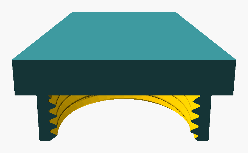
Figure 28: Cap, default variant, cutaway (BOSL2 BACK) showing the bore.
- Coupling
- a fitting that joins two pipes end-to-end. Generally female-female; the reducing coupling joins different sizes; the slip coupling omits the internal stop, used in repair work.
- Cross
a four-port fitting with the three branch ports at 90° to the run. The plumbing equivalent of a tee with one extra outlet.
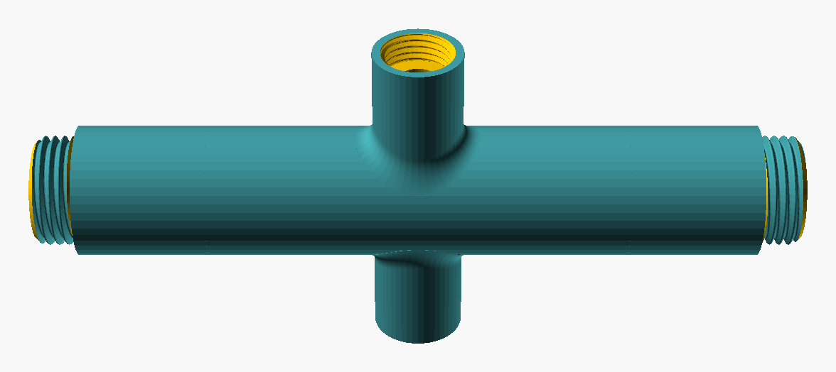
Figure 29: Cross, default variant (single fitting; viewpoint lat 35°, lon 270°). Solid form.
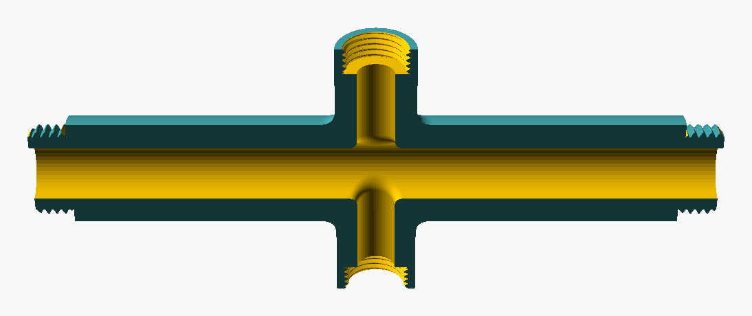
Figure 30: Cross, default variant, cutaway (BOSL2 BACK) showing the bore.
- Elbow
a fitting that changes direction. Common angles: 90°, 45°, 22.5°. Long-radius (LR, centreline radius = 1.5×D) reduces pressure drop and entrained-solid deposition; short-radius (SR, = 1×D) fits in tight spaces and dominates pressurised systems. Both proportions are conventional standards (the multiplier is the pipe diameter D, not the thread diameter). Naming convention notes: "45° elbow" names the bend from straight, not the protractor angle of the joint — a clarification adopted via the Wikipedia coverage map.
Domain note (LR vs SR). The LR/SR distinction correlates with usage domain rather than being a free parameter:
- SR elbows are typical in pressurised systems and tight installations — threaded brass and steel BSPP / BSPT / NPT fittings in domestic plumbing, pneumatic, and light-hydraulic installations are predominantly SR.
- LR elbows are typical in low-pressure gravity-fed systems where low turbulence and minimum entrained-solid deposition matter — drain-waste-vent (DWV), sewage, central vacuum. LR elbows are commonly available in ABS, PVC, CPVC, and copper, not predominantly in BSPP-threaded brass.
Implication for BSPPFit scope. The LR/SR distinction is most-relevant outside the BSPP-centred scope. Within BSPP territory, SR is the default and LR is the special case; the classification is therefore recorded here as a property of an elbow rather than promoted to a separate facet axis. Whether LR/SR deserves its own facet remains open; deciding it in isolation would over-fit, and it is more likely to be resolved together with other length and curvature facets. Source for the materials and usage-domain pairing: Wikipedia Piping and plumbing fitting (informational, paraphrased).
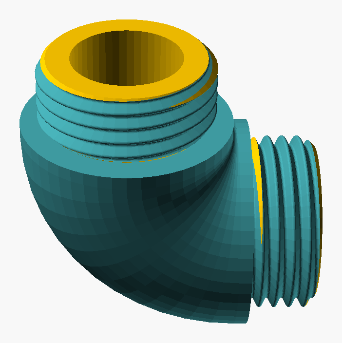
Figure 31: Elbow, default variant (single fitting; viewpoint lat 35°, lon 270°). Solid form.
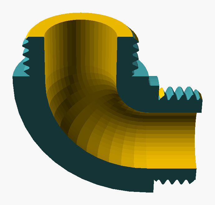
Figure 32: Elbow, default variant, cutaway (BOSL2 BACK) showing the bore.
- Elbow, street
- an elbow with one male port and one female port, allowing a male-female direction change in a single fitting. Equivalent to elbow with mixed gender applied; in BSPPFit's faceted model, a street elbow is F-01 = Elbow + F-02 = Mixed-gender, not a separate F-01 sub-type.
- Fitting (generic)
- any of the parts that join lengths of pipe or interface pipe to equipment: tees, elbows, couplings, unions, reducers, bushings, plugs, caps, hose tails, manifolds. The French equivalent raccord covers the same scope.
- Hex bush
a bushing with a hexagonal external profile for spanner engagement.
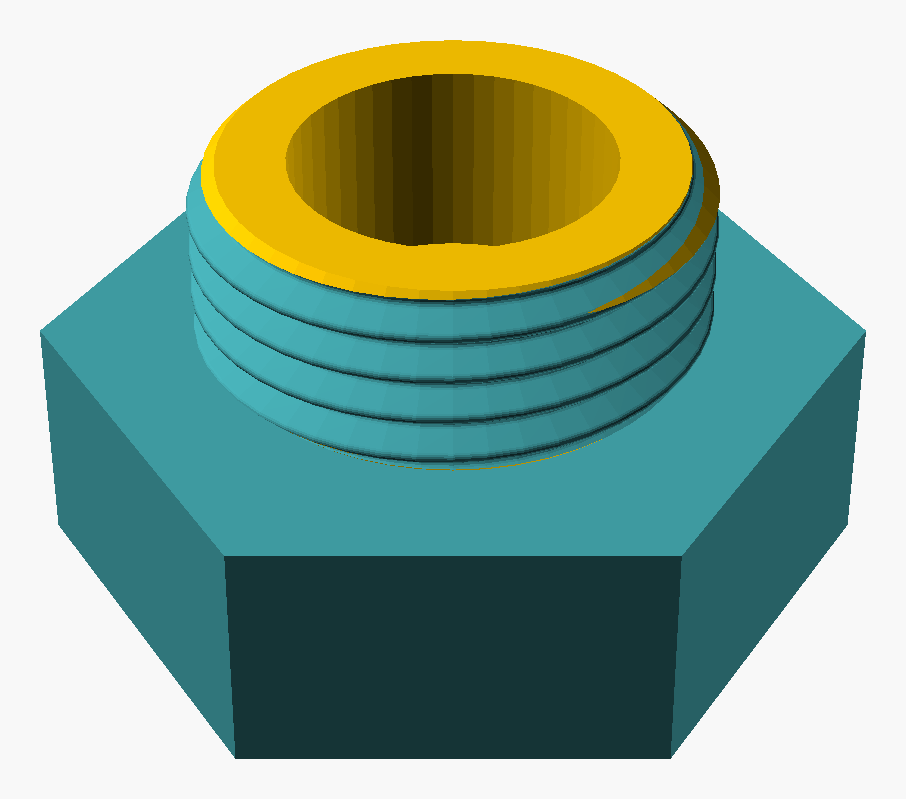
Figure 33: Hex bush, default variant (single fitting; viewpoint lat 35°, lon 270°). Solid form.
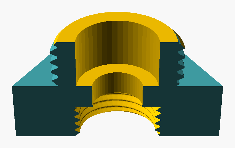
Figure 34: Hex bush, default variant, cutaway (BOSL2 BACK) showing the bore.
- Hose tail (barb)
a fitting with a threaded port on one side and a serrated barb on the other for hose attachment; usually retained by a worm-drive clamp.
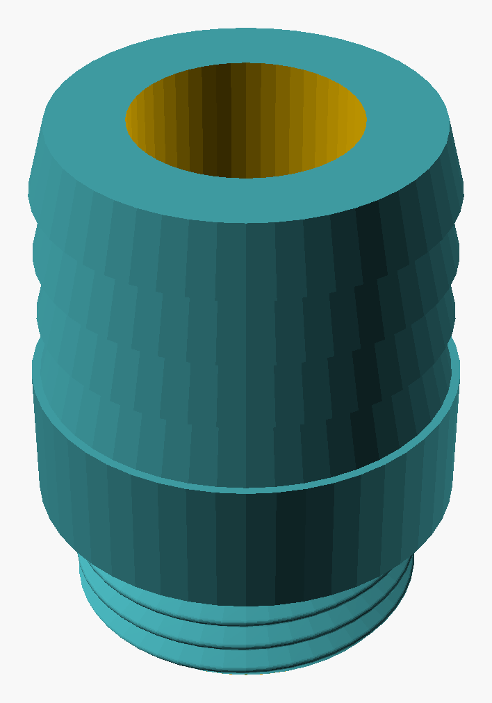
Figure 35: Hose tail, default variant (single fitting; viewpoint lat 35°, lon 270°). Solid form.
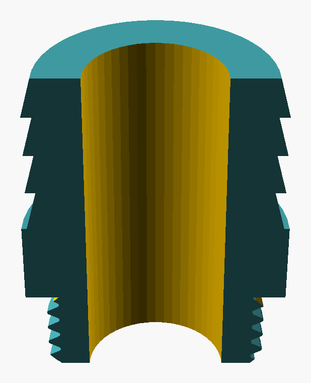
Figure 36: Hose tail, default variant, cutaway (BOSL2 BACK) showing the bore.
- Inlet
- the port through which the working fluid enters a fitting. Tied to flow direction, not to a fixed end. Matters for direction-sensitive fittings (check valves, regulators) and for orienting asymmetric gendered fittings in an installation.
- Manifold
a multi-port fitting consisting of a straight cylindrical pipe run (open or capped at each end) carrying one or more branch ports perpendicular or oblique to the run. In trade usage the term commonly names the multi-branch distribution form (a supply line feeding several consumers, or returns collected into one); in this project Manifold is also the name of the unified geometric class (G-10) of which the trade categories tee (one branch), cross (two opposed branches), and the multi-branch distribution manifold proper are all configurations — they share one parameterisable geometry and differ only in branch count and arrangement. Common downstream of a pneumatic compressor and upstream of individual tools. Distinct from a pneumatic distribution block (a solid rectangular bar with tapped ports), which is a different product family and not modelled here. Unified class adopted at 0.36.0; see the G-10 catalogue entry for the full history and parameter set.
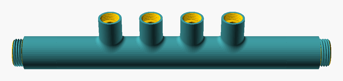
Figure 37: Manifold, default variant (single fitting; viewpoint lat 35°, lon 270°). Solid form.
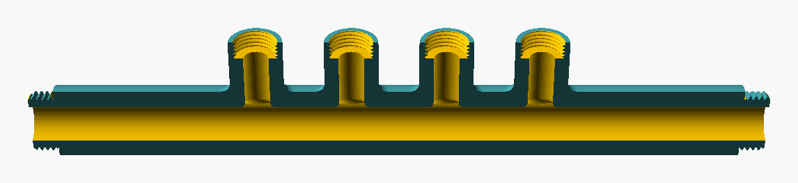
Figure 38: Manifold, default variant, cutaway (BOSL2 BACK) showing the bore.
- Nipple
a short straight fitting with male threads on both ends (M × M). Used to extend a female-female chain. Length sub-variants exist (see close nipple). A "nipple" is male × male by definition; the mixed-gender straight fitting (M × F) is an adapter and the female-female straight fitting (F × F) is a socket — there is no fitting called a "female nipple", though the female-ended straight geometry exists under those other names. Resolved 0.56.0 from project-author trade observation (the F × F and M × F straight fittings are commercially available; they are named socket and adapter, not female nipple). The straight family thus spans the full gender facet.
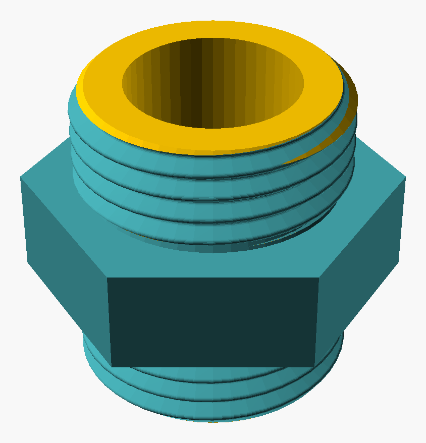
Figure 39: Nipple, default variant (single fitting; viewpoint lat 35°, lon 270°). Solid form.
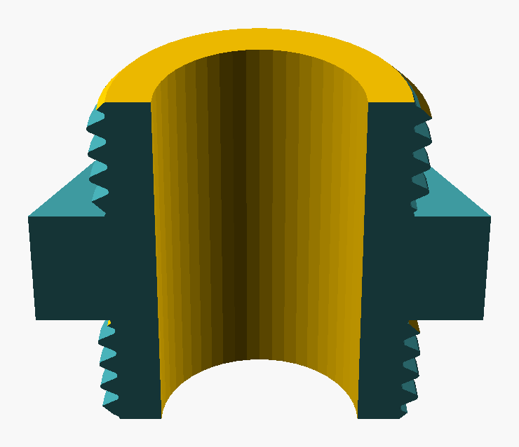
Figure 40: Nipple, default variant, cutaway (BOSL2 BACK) showing the bore.
- Nipple, close
- a nipple in which the threaded sections of the two ends meet without an unthreaded middle section — the threads of the two ends are continuous, with no separation. Used in tight-clearance installations where there is no room for the unthreaded middle band of a standard nipple. A close nipple is a length sub-variant of a nipple, not a separate fitting type; in BSPPFit's faceted model, a close nipple is F-01 = Nipple with a length parameter marked "close".
- Outlet
- the port through which the working fluid leaves a fitting. See Inlet.
- Plug
a male closure that screws into a female port to seal it. Distinct from a cap, which is the female counterpart that screws over a male thread.
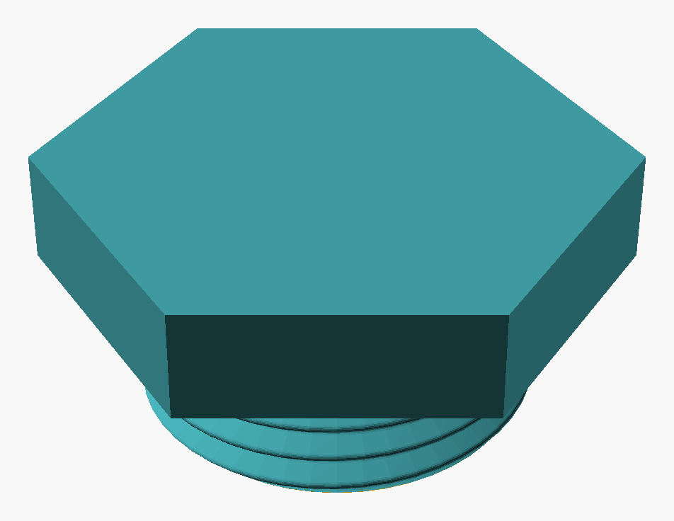
Figure 41: Plug, default variant (single fitting; viewpoint lat 35°, lon 270°). Solid form.
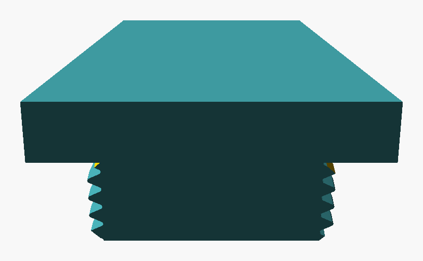
Figure 42: Plug, default variant, cutaway (BOSL2 BACK) showing the bore.
- Port
- the threaded opening of a fitting, valve, or appliance. A fitting has at least two ports; tees, crosses and manifolds have more.
- Reducer
a fitting that changes nominal size between two ports. Concentric keeps the centreline straight; eccentric offsets one port to keep one bore wall continuous (drains better in horizontal lines).
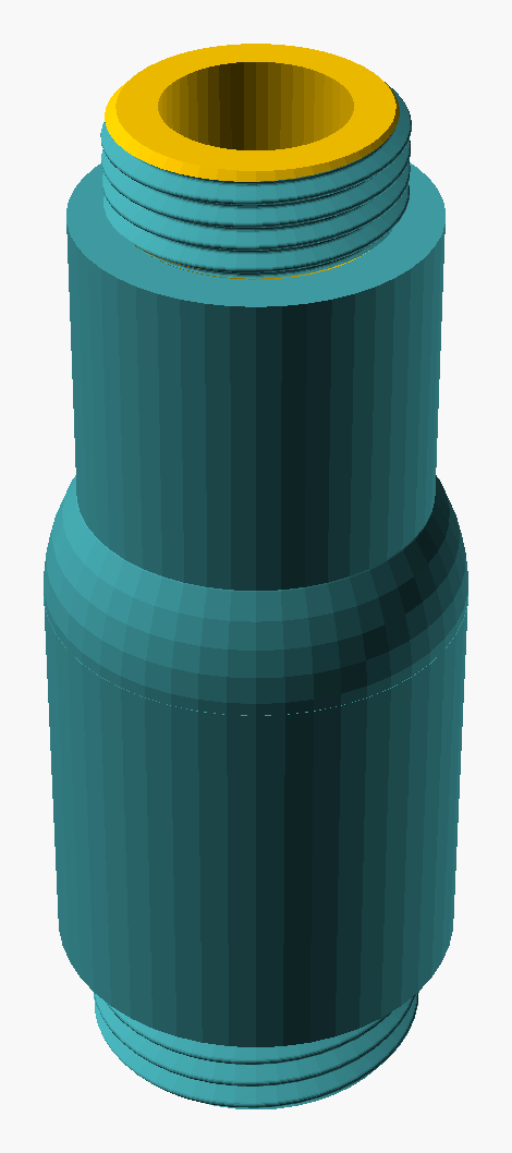
Figure 43: Reducer, default variant (single fitting; viewpoint lat 35°, lon 270°). Solid form.
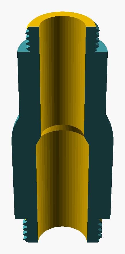
Figure 44: Reducer, default variant, cutaway (BOSL2 BACK) showing the bore.
- Socket
- a short straight fitting with female threads on both ends. Used to join two male-ended fittings.
- Tee
a three-port fitting with the branch at 90° from the run. Equal tee has all three ports the same size; reducing tee has the branch stepped down. Distinct from a wye (45° branch).
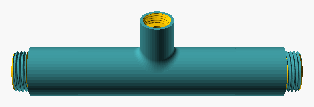
Figure 45: Tee, default variant (single fitting; viewpoint lat 35°, lon 270°). Solid form.
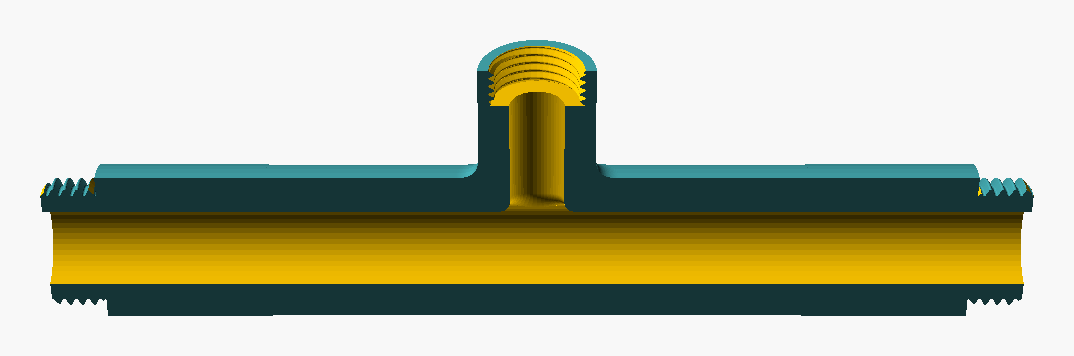
Figure 46: Tee, default variant, cutaway (BOSL2 BACK) showing the bore.
- Union
a three-piece detachable joint allowing the joint to be undone without rotating the connected pipework. The three pieces are two halves with mating seat surfaces plus a collar nut that draws them together.
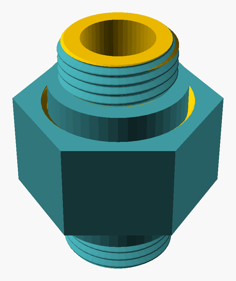
Figure 47: Union, default variant (single fitting; viewpoint lat 35°, lon 270°). Solid form.
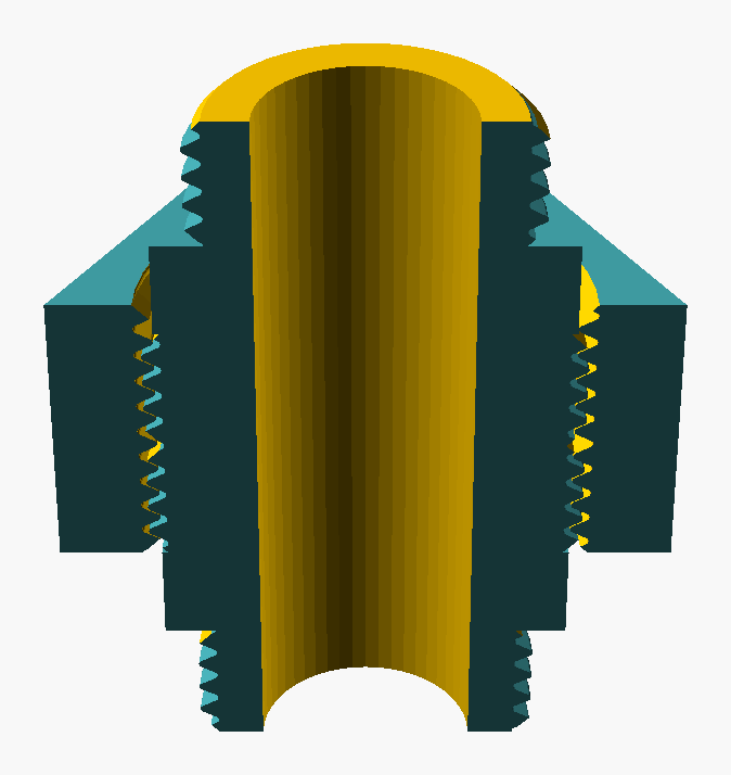
Figure 48: Union, default variant, cutaway (BOSL2 BACK) showing the bore.
- Wye
- a three-port fitting with the branch at 45° from the run, common in drainage applications. Distinct from a tee (90° branch). Surfaced as a borrow-candidate from the Wikipedia coverage map; see Coverage map vs Wikipedia.
15.3. Gender
15.4. Sealing
- Anaerobic pipe sealant
- liquid sealant that polymerises in the absence of air and the presence of metal, locking and sealing threaded joints. Sometimes called by trade names (Loctite 577 and similar).
- Bonded seal washer (Dowty seal)
- a washer with a rubber inner bonded to a metal outer ring, used to seal a parallel-thread fitting against a flat face.
- Compression set
- the loss of resilience an elastomer suffers after sustained compression; an O-ring with high compression set may not re-seal after disassembly and reassembly.
- Cone seat
- a metal-to-metal seal where a conical male end beds against a matching female cone. Common at 60° in hydraulics.
- Gasket
- a soft sacrificial part compressed between two mating faces to form a seal. May be soft (fibre, elastomer, PTFE) for low-temperature service, composite (graphite, graphite-with-metal-mesh) for steam and hot service, or soft metal (copper, aluminium) for very high pressure or temperature.
- O-ring
- a circular elastomer ring seated in a groove, compressed to form a seal.
- PTFE tape (plumber's tape, Teflon tape)
- thin polytetrafluoroethylene tape wrapped around male threads before assembly. Acts as a thread filler and lubricant on tapered threads.
15.5. Materials
- CW614N / CW617N
- standard EN designations for the two most common BSPP brass alloys. CW614N is general-purpose; CW617N is DZR.
- Dezincification
- corrosion process by which zinc is selectively leached from standard brass, leaving a porous copper structure; aggravated by soft, low-pH water.
- Dielectric union
- a union with an insulating insert that breaks the electrical path between dissimilar metals to prevent galvanic corrosion.
- DZR brass
- dezincification-resistant brass (CW617N or
equivalent); marked
DZRorCRon the fitting body. Required for potable water in many jurisdictions. - Galvanic corrosion
- accelerated corrosion of one metal when in electrical contact with a more noble metal in the presence of an electrolyte.
- Galvanised steel
- carbon steel with a zinc coating for corrosion protection. Used for general plumbing and gas in many markets.
15.6. Pressure, temperature, and ratings
- Burst pressure
- the pressure at which a fitting will fail. Typically 4× the working pressure; not a design target.
- High pressure
- in this taxonomy, the 16-40 bar band (heavy pneumatic, light hydraulic, high-pressure water). Very high pressure is the 40-400+ bar band of industrial hydraulics. See What "low", "moderate", and "high" pressure mean here.
- Low pressure
- in this taxonomy, the 1-6 bar band (domestic plumbing, irrigation, central heating). The sub-band below 1 bar is very low (gravity drainage).
- Moderate pressure
- in this taxonomy, the 6-16 bar band (light pneumatic, mains plumbing, general industrial water).
- Pipe class
- collective term for the combination of pressure rating, schedule, and material that defines a pipe's service envelope.
- PN16, PN25, PN40
- nominal-pressure markings: 16 bar, 25 bar, 40 bar respectively. The PN system is European; the American equivalent is class (e.g., Class 150, Class 300).
- Pressure derating
- the reduction in working pressure as temperature rises. Brass and plastic derate sharply; steel and stainless less so.
- Schedule (Sch)
- a pipe wall-thickness class. Schedule 40 is the most common in domestic plumbing; higher numbers indicate thicker walls. Independent from nominal size.
- Working pressure
- the maximum continuous pressure for which a fitting is rated. Synonym: service pressure.
15.7. Approvals and markings
- 3.1
- EN 10204 3.1 material certificate; documents the specific material composition and test results for a batch of fittings.
- ACS
- Attestation de Conformité Sanitaire (France). French potable-water approval.
- DVGW W 534
- German potable-water approval specifically for metallic and combination drinking-water fittings (DVGW = Deutscher Verein des Gas- und Wasserfaches, the German technical-scientific association for gas and water). Where KTW is the broader plastics- in-contact-with-drinking-water umbrella, this approval is finer-grained: it applies to threaded brass fittings, valves, and similar metallic items intended for installation in domestic drinking-water systems. Encountered on French supplier catalogues that distribute German-made fittings.
- KTW
- Kunststoffe-Trinkwasser (Germany). German potable-water approval.
- WRAS
- Water Regulations Advisory Scheme (UK). Marks a fitting as approved for potable water in the UK.
15.8. Application terms
- Compression fitting
- a non-threaded fitting that seals on a metal ferrule compressed against the pipe by a nut. Common in copper pipework. Out of scope for Phase 1; in scope for Phase 2.
- Hydraulic
- relating to liquid (oil, water-glycol) under high pressure; typically 100-400+ bar service.
- Pneumatic
- relating to compressed air or other gas transmission; typically 6-12 bar service.
- Quick-release fitting
- a non-threaded fitting that mates by push or twist. Common in pneumatics; out of scope for Phase 1 (threaded fittings).
- Tri-clamp (sanitary clamp)
- a non-threaded connection used in food and pharma; a gasket between two polished ferrules clamped together. Not part of the present BSPP taxonomy but listed here because users coming from food/pharma contexts often confuse it with threaded BSPP.
15.9. Tools, accessories, and trade terms
Region-specific names are noted in parentheses. Where two names exist for the same thing the entry lists both, with a cross-reference.
- Faucet
- North-American synonym for tap (water outlet) in the kitchen-and-bathroom sense. See Tap.
- Hose clamp
- Commonwealth synonym for worm-drive clamp. North-American hose clamp is the same thing. See Worm-drive clamp.
- Hose clip
- British colloquial synonym for worm-drive clamp, especially in the smaller sizes. See Worm-drive clamp.
- Jubilee clip
- British trade-name-as-argot for a worm-drive clamp. Jubilee Clip is a registered trademark (L. Robinson & Co.) but the term is used generically across UK plumbing and automotive trades. See Worm-drive clamp.
- Plumber's argot — "leak"
- in plumbing trade speech a joint seeps if it lets through a small steady wet trace, weeps if the loss is barely visible, and leaks if there is observable flow. The taxonomy uses "seeps" and "leaks" in the same way.
- Shutoff tap
- a tap used to interrupt flow in a pipework run, typically a quarter-turn ball or gate valve. North-American synonym: shutoff valve. The "tap" sense here is the British/general-English valve-as-tap, not the kitchen faucet sense. See Tap.
- Shutoff valve
- North-American synonym for shutoff tap. See Shutoff tap.
- Spigot
- outdoor-water-outlet synonym
used in North America (
"garden spigot"). In British English spigot can also denote a plain unthreaded male end of a pipe intended to be inserted into a socket; context disambiguates. - Stopcock
- British plumbing term for a shutoff tap installed on the supply side of a building or major branch. North-American synonym: main shutoff valve. See Shutoff tap.
- Tap
- in this document, generic for a manually operated valve fitted into a pipework run — a faucet in North-American English, or a shutoff valve when its role is to interrupt flow rather than dispense it. The British and general-English tap covers both senses; where the distinction matters the document uses shutoff tap explicitly.
- Worm-drive clamp
a band-and-screw clamp used to secure a flexible hose onto a barbed fitting (G-09 hose tail). The slotted band is tightened by a captive screw whose helical lip engages the slots in the band. Sizes are quoted as a clamping-diameter range (e.g., 12-22 mm). Regional synonyms: Jubilee clip (UK), hose clamp (Commonwealth and North America), hose clip (UK colloquial).
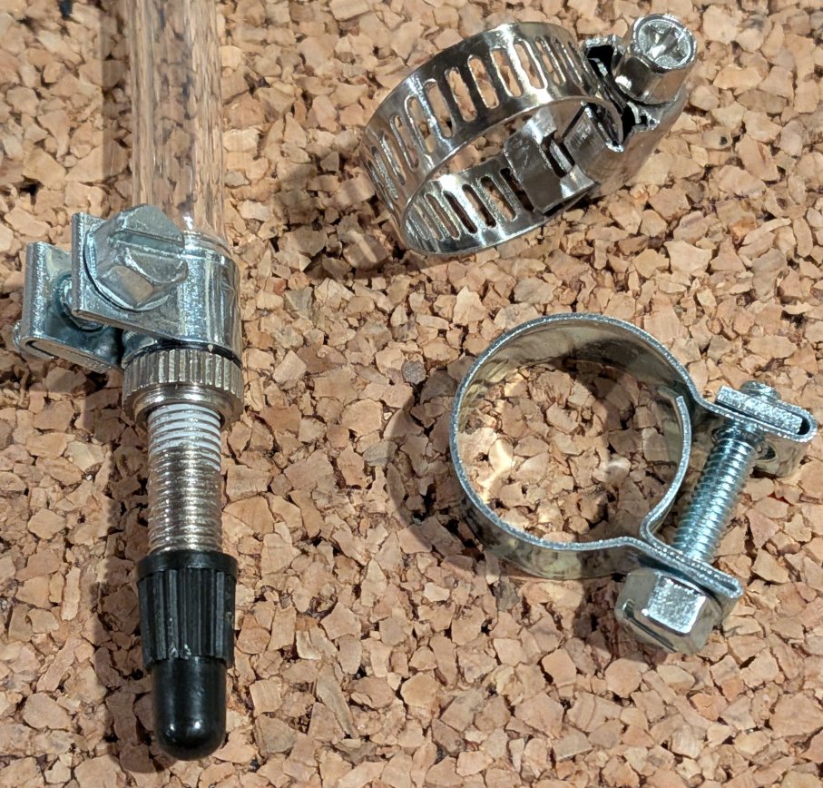
Figure 49: Three hose-clamping mechanisms photographed side by side. Top right: a worm-drive clamp (the slotted band with captive screw whose helical lip engages the band's slots). Left: a wing-nut style clamp shown installed on a hose tail with hose attached. Bottom right: a small two-bolt clamp closing on a copper-coloured hose end. The worm-drive form (top right) is the most common in plumbing and automotive use; the smaller forms appear in petrochemical and pneumatic service. Photograph by Peter Felecan, project author. See also Sources and Attributions.
16. Bilingual Labels — English ↔ French
This section provides French equivalents for every domain term in the glossary above, plus the most-photographed fitting types and tools. The motivating use case is practical: the project author's stock of fittings is labelled in French, and identifying which fitting on the workbench corresponds to which class in the taxonomy requires a French → English lookup. Photography for illustration slots I-03, I-07, I-08 and any future project-author photograph depends on this section.
The French equivalents are sourced from:
- AFNOR standards: NF EN ISO 228-1 (BSPP, filetage gaz cylindrique), NF EN 10226-1 (BSPT, filetage gaz conique), and the body of NF E 03-005 vocabulary that the ISO standards have replaced but whose terminology persists in trade usage.
- Wikipedia FR articles:
Filetage gaz,Collier de serrage,Joint torique,Raccord de tuyauterie. License-compatible (CC BY-SA 4.0). - Office Québécois de la Langue Française, Grand dictionnaire terminologique (https://gdt.oqlf.gouv.qc.ca): used for technical terms where Quebec usage diverges from metropolitan French; flagged in the table when relevant.
- Manufacturer catalogues in metropolitan France (Comap, Watts, Würth FR, Raccordspro, Axesspack, h7g6.fr, multicuves.com): for living trade vocabulary, particularly the genericised brand-names that mirror English Jubilee clip and Dowty seal.
- André Chevalier, Guide du dessinateur industriel (Hachette Technique, 2004 ed.), §48.33 Profils gaz, p.192: a standard French engineering-drawing reference. It names the BSP family profil gaz and gives the profile geometry directly — 55° flank angle, the ISO 228 constants (H = 0.960 491 × P, h = 0.640 327 × P, R = 0.137 329 × P), the parallel form (ISO 228, G) versus the tapered form (ISO 7, R / Rp / Rc, taper 1:16 = 6.25 %), and the designation examples (G 2 1/2 B; R 2 1/2 – Rp 2 1/2 – Rc 2 1/2). The adjacent §48.323 profil en dents de scie (NF L 05-420, buttress thread) is the French source for the sawtooth form noted below.
Format. The table is grouped by the same sub-sections as the English glossary above. Within each group the rows are sorted alphabetically by the English term (the canonical side). To do a French → English lookup, scan the French column. To do an English → French lookup, the row order matches the glossary above.
Regional variants. Where metropolitan-France usage differs from Quebec or other francophone usages, both are listed, with (FR) for metropolitan France and (QC) for Quebec; otherwise the term is the same in both. Trade argot entries (such as collier Serflex, joint Dowty) parallel the English Jubilee clip entry: a brand name that became generic.
Honest limit. I (the assistant who drafted this section) am not a francophone professional plumber. The terminology below is derived from documentary sources and verified against multiple references where possible, but it has not been reviewed by a francophone trade practitioner. Where I have material doubt about a term I flag it with a parenthetical [à vérifier]. The project author is invited to correct the entries against his workbench over time; corrections become journal entries, not silent edits.
16.1. Thread forms (~ formes de filetage )
| English term | French equivalent | Notes |
|---|---|---|
| BSPP | filetage gaz cylindrique ; BSP cylindrique ; BSPP | Standard ISO 228-1 / NF EN ISO 228. Désignation : G suivi de la taille (G1/2, G3/4…). |
| BSPT | filetage gaz conique ; BSP conique ; BSPT | Standard ISO 7-1 / NF EN 10226-1. Désignation : R (mâle), Rp (femelle cylindrique), Rc (femelle conique). |
| NPT | NPT (terme conservé) ; filetage conique américain | Standard ANSI/ASME B1.20.1. Désignation : 1/2 NPT, 3/4 NPT… |
| Whitworth thread profile | profil Whitworth ; profil de filet à 55° ; pas Whitworth | Angle de filet 55°, crêtes et racines arrondies. Base commune de BSPP et BSPT. |
| Sellers thread profile | profil Sellers ; profil de filet à 60° ; filetage américain | Angle de filet 60°, crêtes et racines tronquées plates. Base de NPT et UN/UNF. Note d'usage : en plomberie domestique métropolitaine française, filetage américain s'emploie pour désigner les filetages de type NPT dans des situations limitées ; pour le gaz, l'usage est BSPP avec joint plat, pas NPT. (Information confirmée par un chauffagiste, itération 0.8.6.) |
| Pas du gaz (historical FR) | pas du gaz | Argot de métier français pour filetage gaz ; reste vivant dans les ateliers, déprécié dans les normes. |
16.2. Geometry and ports (~ géométrie et orifices )
| English term | French equivalent | Notes |
|---|---|---|
| Banjo bolt | vis banjo ; raccord banjo | Vis creuse traversée par un canal transversal, étanchée par joint collé. |
| Bore | alésage ; diamètre intérieur | Diamètre intérieur du passage de fluide. |
| Bushing (reducing bush) | réduction mâle-femelle ; douille de réduction | Filetage mâle extérieur, femelle intérieur de taille inférieure. |
| Cap | bouchon femelle ; capuchon | Se visse sur un filetage mâle pour fermer un orifice. |
| Coupling | manchon ; raccord de jonction | Manchon droit reliant deux extrémités de tube ; généralement femelle/femelle. |
| Cross | croix ; raccord en croix | Quatre orifices à 90° ; assemblage en T inversé. |
| Elbow | coude (90°) ; coude à 45° ; coude à 90° | Changement de direction de la canalisation. Précisez l'angle si différent de 90°. |
| Fitting (generic) | raccord ; raccord de tuyauterie | Terme générique recouvrant tee, coude, manchon, etc. |
| Hex bush | réduction à six pans ; bague de réduction hexagonale | Bushing avec corps hexagonal pour clé à pipe / clé plate. |
| Hose tail (barb) | embout cannelé ; raccord cannelé ; raccord à barbillon (QC) | Embout strié pour insertion dans un tuyau souple, retenu par un collier de serrage. |
| sapin (argot) ; tétine (argot) | Argot de métier français pour embout cannelé ; courant chez les pompistes et plombiers. | |
| Inlet | entrée ; orifice d'entrée | Côté du raccord par lequel le fluide entre. |
| Manifold | distributeur ; collecteur ; nourrice (FR plomberie) | Nourrice est le terme courant en plomberie domestique en France pour le distributeur multi-orifices. |
| Nipple | mamelon ; petit raccord double-mâle | Court raccord droit avec filetage mâle aux deux extrémités. |
| Extension nipple (long nipple, barrel nipple) | rallonge (mâle/mâle, mâle/femelle) ; allonge ; rallonge sanitaire | Long version of nipple: a length of pipe with male threads at both ends (or male/female), used to gain reach beyond the standard nipple length. Allonge de compteur specifically: a meter-extension nipple. German: Hahnverlängerung. |
| Outlet | sortie ; orifice de sortie | Côté du raccord par lequel le fluide sort. Voir entrée. |
| Plug | bouchon mâle | Se visse dans un taraudage femelle pour fermer un orifice. German: Stopfen. |
| Port | orifice ; raccordement | Ouverture filetée d'un raccord, d'une vanne ou d'un appareil. |
| Reducer | réduction (concentrique / excentrique) | Change la taille nominale entre deux orifices. Excentrique pour conduites horizontales (drainage). |
| Socket | manchon femelle-femelle ; manchon double-femelle | Manchon court avec filetage femelle aux deux extrémités. |
| Swivel nut (compression-fitting style) | écrou prisonnier ; écrou tournant | Captive nut tightened over a deformable ring or seal to make a compression-style joint, common on PE-X / multilayer / annealed-copper connections to BSPP-threaded valves. German: Gelenkmutter. |
| Tee | té ; raccord en T | Trois orifices, dérivation à 90° depuis le passage principal. |
| Union | union ; raccord union ; raccord trois-pièces | Joint démontable en trois pièces, séparable sans rotation des tuyaux raccordés. |
| Wallplate elbow | coude applique ; coude mural | Elbow with a flat flange for fastening to a wall, used at the terminal point of a pipe run before the visible fixture (tap, mixer). German: Wandwinkel. |
16.3. Gender (~ genre du filetage )
| English term | French equivalent | Notes |
|---|---|---|
| Female | femelle ; taraudage (intérieur) | Filetage intérieur. Taraudage désigne précisément l'opération et le filetage femelle qui en résulte. German shorthand: IG = Innengewinde. |
| Male | mâle ; filetage (extérieur) | Filetage extérieur. Filetage employé seul désigne souvent le filetage mâle par défaut. German shorthand: AG = Außengewinde. |
| Mixed gender (M × F) | mâle-femelle ; mixte | Un orifice mâle et un orifice femelle sur le même raccord. Comisa marquage type AG/IG pour M × F. |
16.4. Sealing (~ étanchéité )
| English term | French equivalent | Notes |
|---|---|---|
| Anaerobic pipe sealant | pâte d'étanchéité anaérobie ; résine anaérobie ; Loctite (argot) | Polymérise en l'absence d'air et présence de métal. Loctite 577, Loctite 567, etc. |
| Bonded seal washer | joint collé ; rondelle Dowty ; joint Dowty ; joint Usit (argot) | Rondelle métal/élastomère. Joint Usit est un nom de marque devenu générique, parallèle à Dowty. |
| Compression set | déformation rémanente après compression ; tassement | Perte d'élasticité d'un élastomère après compression prolongée. |
| Cone seat | siège conique ; portée conique ; cône d'étanchéité | Étanchéité métal-métal entre deux cônes male/femelle. Courant en hydraulique 60°. |
| Gasket | joint plat ; joint d'étanchéité | Pièce sacrificielle comprimée entre deux faces. Joint plat pour les modèles minces et plats. |
| O-ring | joint torique ; (joint) O-ring | Joint annulaire en élastomère de section circulaire. |
| PTFE tape (Teflon tape) | ruban PTFE ; ruban Téflon ; téflon (argot) | Marque Téflon devenue générique. Bande mince utilisée sur les filetages mâles. |
| Sealant (generic) | produit d'étanchéité ; pâte d'étanchéité | Terme générique recouvrant pâte filasse, anaérobies, ruban, etc. |
| Tow + paste (filasse + pâte) | filasse + pâte d'étanchéité ; filasse | Étanchéité traditionnelle française : filasse de lin enduite de pâte. Vivante en plomberie domestique. |
16.5. Materials (~ matériaux )
| English term | French equivalent | Notes |
|---|---|---|
| Brass | laiton | Alliage cuivre-zinc. Matériau dominant des raccords domestiques en France. |
| CW614N / CW617N | CW614N / CW617N | Désignations EN identiques en français. CW617N = laiton DZR. |
| Dezincification | dézincification | Corrosion sélective du zinc dans le laiton. Aggravée par eaux douces et acides. |
| Dielectric union | raccord diélectrique ; union diélectrique | Union avec isolant interne pour interrompre la liaison galvanique entre métaux dissemblables. |
| DZR brass | laiton anti-dézincification ; laiton DZR | Marqué DZR ou CR. Exigé pour eau potable dans plusieurs juridictions. |
| Galvanic corrosion | corrosion galvanique | Corrosion accélérée par contact entre deux métaux différents en présence d'électrolyte. |
| Galvanised steel | acier galvanisé | Acier au carbone avec revêtement de zinc. |
| Stainless steel | acier inoxydable ; inox | Inox est l'usage commercial dominant en France. |
16.6. Pressure, temperature, and ratings (~ pression, température, classification )
| English term | French equivalent | Notes |
|---|---|---|
| Burst pressure | pression d'éclatement ; pression de rupture | Pression à laquelle un raccord cède. |
| High pressure | haute pression | Bande 16-40 bar dans cette taxonomie. |
| Low pressure | basse pression | Bande 1-6 bar. |
| Moderate pressure | pression modérée ; moyenne pression | Bande 6-16 bar. |
| PN16, PN25, PN40 | PN16, PN25, PN40 | Désignations européennes identiques en français. |
| Pipe class | classe de conduite ; série | Combinaison pression / épaisseur / matériau. |
| Pressure derating | déclassement en pression ; abaissement de la pression admissible | Réduction de la pression admissible avec la température. |
| Schedule (Sch) | schedule (Sch) ; classe d'épaisseur | Schedule est le terme américain conservé même en français technique. |
| Working pressure | pression de service ; pression de travail | Pression continue maximale admissible. |
16.7. Approvals and markings (~ agréments et marquages )
| English term | French equivalent | Notes |
|---|---|---|
| 3.1 (EN 10204 cert) | certificat 3.1 ; attestation 3.1 | Certificat matière documentant composition et essais d'un lot. |
| ACS | ACS (Attestation de Conformité Sanitaire) | Agrément français pour eau potable. Le sigle ACS est l'usage courant en France. |
| DVGW W 534 | DVGW W 534 | Agrément allemand spécifique aux raccords métalliques pour eau potable. Sigle conservé en français. |
| KTW | KTW (Kunststoffe-Trinkwasser) | Agrément allemand. Le sigle est conservé en français. |
| WRAS | WRAS | Agrément britannique. Le sigle est conservé en français. |
16.8. Tools, accessories, and trade terms (~ outils, accessoires, vocabulaire de métier )
| English term | French equivalent | Notes |
|---|---|---|
| Faucet | robinet ; mitigeur (mixer faucet) | Mitigeur pour le robinet eau-chaude/eau-froide unique. |
| Hose clamp / Hose clip | collier de serrage (générique) | Terme parapluie, voir Worm-drive clamp. |
| Jubilee clip | collier Serflex ; collier à vis sans fin (terme technique) | Argot français parallèle à l'anglais. Serflex est une marque devenue générique. |
| Plumber's argot — "leak" | suinte (seeps) ; goutte (weeps) ; fuit (leaks) | Hiérarchie : suinter (trace humide) < goutter (gouttes formées) < fuir (écoulement visible). |
| Shutoff tap | robinet d'arrêt ; vanne d'arrêt | Robinet d'arrêt en plomberie domestique ; vanne d'arrêt pour les modèles industriels. |
| Shutoff valve | vanne d'arrêt ; robinet d'arrêt | Voir Shutoff tap. Synonyme nord-américain. |
| Spigot | robinet de jardin ; robinet extérieur ; robinet (portion mâle d'un emboîtement) | Sens 1 : robinet d'extérieur ; sens 2 : extrémité mâle d'un raccord à emboîtement. |
| Stopcock | robinet d'arrêt principal ; vanne d'arrêt général | Robinet d'arrêt sur l'arrivée d'eau d'un bâtiment ou d'une dérivation principale. |
| Tap | robinet | Terme générique. La distinction shutoff tap vs faucet est rendue en français par le contexte. |
| Worm-drive clamp | collier à vis sans fin ; collier de serrage à vis sans fin | Terme technique normalisé. Voir Jubilee clip pour l'argot. |
16.9. Application terms (~ termes d'application )
| English term | French equivalent | Notes |
|---|---|---|
| Compression fitting | raccord à compression ; raccord à bicône ; raccord olive | Raccord non fileté, étanchéité par bague (olive) comprimée. |
| Push-fit fitting | raccord à emboîtement rapide ; raccord push-fit | Raccord à connexion rapide sans outil. |
| PTFE | PTFE ; téflon (marque devenue générique) | Polytétrafluoroéthylène. |
| Sweat fitting | raccord à braser ; raccord à souder | Pour assemblage par brasure tendre, principalement sur cuivre. |
| Solvent-weld fitting | raccord à coller ; raccord à coller PVC | Pour assemblage par collage chimique, principalement sur PVC pression. |
16.10. Practical sizing note — French DI×DE designations and the European DN system
In metropolitan-French plumbing trade, BSPP sizes are conventionally written as the pair diamètre intérieur × diamètre extérieur du filetage in millimetres (e.g. 15 × 21), rather than by the BSPP G-designator (e.g. G1/2) or the European DN designator (e.g. DN 15). The DI×DE form is a presentation convention, not a separate thread standard: a fitting marked 15 × 21 is the same physical fitting as one marked G1/2 or DN 15; only the labelling differs.
No "15/21 family". The phrase "the French 15/21 family" is not established trade vocabulary — French commercial sources use "norme", "dimension", "format", "désignation métrique", or simply "15/21", not "famille". Use "DI×DE designation" or "DN designation" depending on which is meant.
Three coexisting designation systems. The same physical half-inch BSPP thread carries three different labels in different European contexts:
- BSPP G-designator, e.g.
G1/2. The standard ISO 228 mark; appears engraved on machined fittings across Europe. - European DN designator, e.g.
DN 15. The diamètre nominal system of ISO 6708, used as a code across European catalogues. Not a physical measurement — ISO 6708 says explicitly that the number "is used for reference purposes" and only approximates a diameter. - French DI×DE designation, e.g.
15 × 21or15/21. Dual-mm notation: 15 mm approximate inside diameter of the pipe + 21 mm approximate thread outer diameter. Vivid in French domestic-plumbing packaging; less common in German or northern-European catalogues.
Cross-reference between the three is exact for any given fitting; the table below records the standard correspondences.
Why not "Imperial". Labelling the second column Imperial would be historically defensible (the G-designator's number is the legacy half-inch nominal-bore from before thread-standard separation) but misleading: G1/2 is the BSPP designator under the modern ISO 228 metric standard, and reading "1/2" as "half an inch" is exactly the confusion the F-04 Nominal Size section warns against. The column header is therefore BSPP designator, not Imperial.
Is this only French? The DI×DE form is
metropolitan-French specifically. The DN form is general
European (ISO 6708; widely used in Germany, Italy,
Netherlands, etc.). The G-designator is universal across
the BSPP world. German practice illustrates the
contrast: a German fitting catalogue typically lists a
½-inch BSPP thread as G 1/2 Zoll, DN 15, 1/2" AG (where
AG = Außengewinde, "external thread"); the
/15 × 21/ form is rare in German commercial use.
French commercial use, by contrast, frequently shows
only the DI×DE form on packaging — which is the
identification problem this section addresses.
| BSPP designator | DN code | French DI×DE | Notes (metropolitan-France usage) |
|---|---|---|---|
G1/4 |
DN 8 | 8 × 13 | Small bibcocks, gauges, instrumentation. |
G3/8 |
DN 10 | 12 × 17 | Appliance hookups (washing machines, dishwashers); flexibles. |
G1/2 |
DN 15 | 15 × 21 | Most common domestic-plumbing size in France: sink and basin taps, washing-machine inlets. |
G3/4 |
DN 20 | 20 × 27 | Garden taps, larger washing-machine inlets, some heating distribution. |
G1 |
DN 25 | 26 × 34 | Mains supply branches, larger garden connections. |
G1 1/4 |
DN 32 | 33 × 42 | Larger industrial and agricultural connections. |
G1 1/2 |
DN 40 | 40 × 49 | Industrial and agricultural use. |
G2 |
DN 50 | 50 × 60 | Large mains and industrial use. |
Note: the DN number approximates the inside diameter in millimetres (DN 15 ≈ 15 mm bore); the French-DI×DE-first-number is the same approximation under a different label. Neither is a precise physical measurement: actual bore depends on pipe wall thickness, which depends on pipe class. The second number in the French form (the 21 in 15 × 21) is the rounded thread outer diameter, not the pipe outer wall diameter — a common confusion. See F-04 §Bore and thread-OD notation for the full discussion of 15/21 as bore and thread OD, and Facet — Nominal Size for why the nominal label and the physical measurement diverge.
The metropolitan-French identification workflow remains: read the DI×DE designation off the fitting → cross- reference this table → find the BSPP G-designator → look up the per-size dimension table in F-04. German catalogues typically print all three labels on the same fitting, so the cross-reference is implicit.
16.11. What this section does not cover
- Pipe materials beyond brass and steel. The PVC, PEX, polyethylene, and copper sweat-fitting vocabularies are within plumbing's broader French terminology but out of scope for BSPP-centred BSPPFit.
- Hydraulic / pneumatic specialised vocabulary beyond what intersects with BSPP fittings.
- Sanitary fittings (DIN 11581 etc.) which have their own French vocabulary.
- Items flagged [à vérifier] above remain pending project-author verification against the workbench; corrections welcome as journal entries.
17. Sources and Attributions
This document includes externally-sourced illustrations under their original licenses. Each is reproduced with the attribution required by its license; the originals are reachable via the URLs below. The body of the document retains short attribution lines in the figure captions; this section consolidates the full credit.
BSPPFit as a whole is licensed under GNU GPL v3 or later
(see COPYING at the project root). The externally-sourced
illustrations are not relicensed by inclusion — they
retain their original licenses, and any redistributor of the
project carries the obligation to preserve the credit and the
license link. CC BY-SA 4.0 has been declared one-way
GPL-v3-compatible by Creative Commons since 2015, so the
aggregate is licensable consistently.
The full per-slot record (URL, format, role, attribution string template) is maintained in Doc/Illustrations/Catalogue.org.
| Slot | File | Title / subject | Author / contributor | License | Source |
|---|---|---|---|---|---|
| I-01 | WhitworthThread.svg |
55° Whitworth thread profile | Original: Tjt263; vectorised by AntiCompositeNumber | CC BY-SA 4.0 | Wikimedia Commons |
| I-02 | BondedWasher.png |
Bonded seal washer cross-section | Wikipedia user Brotherpete (created with Paint.net) | Public domain | Wikipedia: Bonded seal / Wikimedia Commons |
| I-04 | BSPPMaleStraightThread.png |
BSPP male straight-thread fitting | Kees08 | CC BY-SA 4.0 | Wikimedia Commons (downsampled by project author from the 65 MB original) |
| I-05 | WormDriveHoseClamp.png |
Three hose-clamping mechanisms | Peter Felecan (project author) | GPL v3 or later | Project author's own photograph |
| I-09 | ThreeThreadForms.png |
Historical three-thread-form plate | William Sellers (1864) | Public domain | Wikimedia Commons |

Pending slots. I-03 (cone seat / 37° JIC), I-06 (pipe fitting types overview), I-07 (O-ring cross-section), I-08 (BSPT taper geometry) remain unfilled. Their status is tracked in Catalogue.org. The project author plans to provide some of these as own photographs; the remainder will be replaced with renders extracted from the BSPP model library when that deliverable is in place.
17.1. Bibliographic references (Topological Foundations)
The Topological Foundations part draws on standard sources in topology; they are listed here, with the inline markers in that part pointing to this section, per the project convention of inline attribution plus a collected list. The cobordism and Frobenius-algebra framing is standard; what is original is its instantiation on the BSPP fitting catalogue.
- Michael F. Atiyah, Topological quantum field theories, Publications Mathématiques de l'IHÉS 68 (1988), 175–186. The TQFT axioms casting a field theory as a functor from a cobordism category — the source of the "objects are manifolds, morphisms are cobordisms" reading of fittings.
- Joachim Kock, Frobenius Algebras and 2-D Topological Quantum Field Theories, London Mathematical Society Student Texts 59, Cambridge University Press, 2003. The textbook treatment of the two-dimensional cobordism category, the pair of pants as generator, and the equivalence of 2D TQFTs with commutative Frobenius algebras.
- Lowell Abrams, Two-dimensional topological quantum field theories and Frobenius algebras, Journal of Knot Theory and its Ramifications 5 (1996), 569–587. The presentation of the two-dimensional cobordism category by generators and relations.
Jean Gallier and Dianna Xu, A Guide to the Classification Theorem for Compact Surfaces, Geometry and Computing 9, Springer-Verlag,
- The classification of compact surfaces (with and without
boundary) by genus and boundary-circle count.
- William S. Massey, A Basic Course in Algebraic Topology, Graduate Texts in Mathematics 127, Springer-Verlag, 1991. Standard reference for the classification of surfaces and the genus invariant.
- For the engineering reading — pipe networks as graphs whose nodes
carry a valence (a plain pipe degree two, a branch degree three or
more) — the framing is common to the hydraulic-network and CAD
feature-recognition literature rather than owed to one canonical
work, but two significant sources ground it:
- On the hydraulic side, Hardy Cross, Analysis of Flow in Networks of Conduits or Conductors, University of Illinois Engineering Experiment Station, Bulletin 286 (1936), is the foundational treatment of a pipe network as a graph with conservation of flow at each junction node — the first practical engineering method for looped pipe networks.
- On the solid-modelling side, Kevin Weiler, Edge-Based Data Structures for Solid Modeling in Curved-Surface Environments, IEEE Computer Graphics and Applications 5 (1985), no. 1, 21–40, represents a solid as a face-adjacency graph — the discrete structure behind the solid-body framing's "graph of faces and adjacencies".